Section 2-4 - Resistance & Kirchhoff's Laws
Current
Current in Metals and Other Materials
Resistance and Ohm's Relationship
Power Dissipated as Thermal Energy
Combinations of Resistors
Batteries
Kirchhoff's Rules
Current
So far, we have been discussing static electricity, charges in
particular
static arrangements which were placed that way by having been moved
very
slowly. Now, we want to start discussing charges which do
move.
It would be nice to be able to describe the rate of that motion, a
quantity
we shall call the current, and which we shall naively define as
the amount of charge which passes a given point per second:
I = Q/t.
The unit of current is the ampere, or amp, and 1A =
1coulomb/1second.
We discussed long ago that Franklin labeled his two charges positive
and negative arbitrarily. Unfortunately, we now know that the
negatively
charged electrons are the charges which move most often, but by the
time
this was realized, 150 years of convention was ground into the
equations
we use. So we now speak of the real current and more
often
of the conventional current, which is assumed to be moving
positive
charge. So, for example, if 5 coulombs of electrons pass me in 3
seconds moving to the right, then the current is
I = Q/t = 5C/3s = 1.67 amps to the left.
What is the current if, in 2 seconds, 5 coulombs of electrons pass
me
to the left while 8 coulombs of protons pass me to the right?
Currents in Metals and Other Materials
In a previous discussion, we saw how charges re-distribute themselves
in
a metal (and to a lesser degree in dielectrics) to eliminate the
electric
field in the metal. In that situation, the charges built up on
the
surfaces of the metal, but could go no farther. However, we shall
now connect the two sides of the metal with wires so that the charge
may
continue on its way:
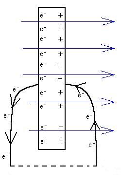
If we were to connect the two wires together, the electrons would
eventually
find themselves attracted back to the right hand side of the
metal.
In any event, since the charges are not allowed to build up on the
surfaces
of the metal, the system never comes to equilibrium, no internal
E-field
is generated, and the net E-field is not required to go to zero.
Certainly, it is not required so to do in a non-metal, anyway.
The ease with which electrons (or other charges) can move through a
material is called the electrical conductivity, s.
More often, though, we'll refer to its reciprocal, the electrical
resistivity,
r,
which is a measure of the difficulty with which charge moves
through
a material. In order of increasing resistivity, the categories of
classification are: super-conductors, conductors (metals), semi-conductors,
semi-insulators,
and
insulators.
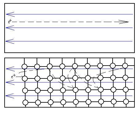
The model we will use is applicable to metals at very low temperatures,
but it gives an idea of what happens in other materials as well.
Consider a region which is empty except for electrons. Now turn
on
an external electric field. Each electron feels a force and
accelerates
quickly to a very high speed. Now, place a lattice pattern of
large
atoms in that region. Since metallic atoms occupy a few percent
of
the volume (still lots of space between the atoms), there is a fairly
high
probability that the electron will collide with an atom without having
had to move very far. This collisions will scatter the electrons
in different directions and will result in a loss (actually a
conversion)
of energy.
First, this process slows the electrons down to an average
velocity
of a few millimetres per second. Second, the energy lost by the
electrons
is gained by the atoms; this shows up as an increase in the vibration
of
the atoms, which we know from past discussions can be detected
macroscopically
as an increase in the metal's temperature. We'll discuss
how
much energy is 'lost' as thermal energy later.
This model also helps to explain an interesting effect. As the
temperature of a metal increases, the electrical resistivity
increases.
We naively explain that, as the temperature increases, the amount of
vibration
of the atoms increases, so that they occupy a larger effective volume,
thereby making collisions with passing electrons even more
likely.
Often, we can approximate that behaviour with the empirical
relationship:
r(T) = ro
(1+aTo
(T
- To)),
where alpha is the temperature co-efficient for resistivity
for a particular material at a particular reference temperature.
Now that we understand this model, let's correct some of the faulty
assumptions it uses. The collisions generally are not with the
atoms,
but with defects in the lattice structure, such as a spot where
an atom is missing, or where there is an extra atom, or where a
different
type of atom (an impurity) has been substituted for a correct
type.
Even then, the model is only good for metals at low temperatures; at
higher
temperatures, the electrons mostly scatter off each other.
Resistance and Ohm's Relationship
Every piece of some material with the same composition, at the same
temperature,
et
c., will have the same conductivity or resistivity (it is an
intrinsic or characteristic
property). However, it is often convenient to use a quantity
which
is sample specific, the conductance
(symbol S, unit the Siemens). The conductance is the
proportionality constant between the potential difference applied
across an object and the resulting current:
I = S DV.
Much more often, the quantity used instead is the resistance
(symbol R, unit the ohm W),
which we shall define as the ratio of the potential difference applied
across a sample to the current that that potential difference causes:
R = DV/I.
Clearly, the resistance and the conducatnce are reciprcal values.
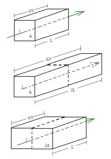
How is resistance related to the resistivity? Consider a block of
material
as shown with a potential difference DV
across
the ends and a current I flowing through the end face as shown in the
top figure.
Certainly, the resistance will depend on the characteristics of the
material; if the resistivity is higher, the resistance of any given
piece
of material should also be higher by the same factor, so we can say
that
R ~ r.
In the second figure, we double the length L of the piece of
material.
If the same potential difference DV is
applied
across the ends, the electric field inside the material will be half as
great, since
E = V/d = DV/2L,
(compared to DV/L in the original piece),
in which case the force on each electron is half as great and the
acceleration
is on average half as great and the average velocity of the electrons
is
half as great as before (see note
below). As a result, it takes twice the time as before for a
given
amount of charge to pass through the sample, and correspondingly, the
current
is half as big, and so R is twice as big. Our conclusion is that
the resistance R is proportional to the length L of the sample:
R ~ L.
In the third figure, the length is returned to its former value and
the cross-sectional area is doubled. It seems clear that the
total
current will be the sum of the currents through each of the
original-sized
sections, that is, double the original current. So, we see that
the
current is doubled, and correspondingly the resistance is halved.
More generally, the resistance is inversely proportional to the
cross-sectional
area:
R ~ 1/A.
Combining these relationships results in:
R = rL/A,
for a rectangularly shaped sample. For more complicated shapes,
we'd have to consider each part and combine the results (see below).
Note that, if the object above were rotated so that the potential
difference
were applied across a different pair of ends, the resistance may well
have
a different value:
RX = rLX/LYLZ
vs
RY = rLY/LXLZ
for example.
So R depends not only on the dimensions of the sample, but on its
orientation
as well.
For many objects, the resistance is a constant (or approximately
so),
and the current is proportional to the applied potential difference:
DV = R I.
Such objects are called ohmic or are said to obey Ohm's
'Law.'
I have placed the word 'law' in quotation marks because this
relationship,
unlike real laws in physics, is not always true. Better to refer
to Ohm's Relationship. In fact, most of the interesting
applications
of this principle are in materials and structures that do not obey
Ohm's
Relationship.
Power
We mentioned that the electrical potential energy of these charges is
converted
into thermal energy. How much energy is so produced? If
charge
Q crosses a potential difference V, it loses QV of potential energy (DEPE
= - QV) and its overall dirft-related kinetic energy component remains
constant (at about zero). The power generated as thermal energy
is
then
P = W/t = -DEPE/t = +QV/t = [Q/t]V = IV.
This relationship is always correct. If the material is ohmic,
though, we can also write that
P = IV = V2/R = I2R.
Combinations of Resistors
We consider two basic arrangements of combinations of resistors: series
and parallel, somewhat similar to the combinations of capacitors we
examined.
We would like to see what value resistance Req will do the
same
job as the combinations, i.e., for a given potential
difference,
allow the same current though.
Consider the parallel arrangement shown below:
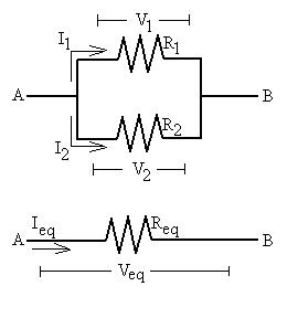
We see a current Ieq flowing into the combination, with
I1 passing through R1 and I2 passing
through
R2. By conservation of charge, we know that
Ieq = I1 + I2,
since we can't create or destroy charge, and there's nowhere for it
to be stored. Also, we know that the potential difference across
the pair Vtot is the same as the difference across each
individually
(V1 and V2),
Veq = V1 = V2,
since the electric field is a conservative field (and therefore the
work done taking a charge slowly from A to B is the same regardless of
path). Lastly, for each we can write Ohm's Relationship:
Veq = IeqReq; V1
= I1R1; V2= I2R2
So, let's start:
Ieq = I1 + I2,
Veq/Req= V1/R1
+
V2/R2
All Vs equal, so they cancel:
1/Req= 1/R1 + 1/R2.
This shows that the equivalent resistence of a parallel pair is less
that either resistance by itself. This should make sense, because
the opening up of a new path for the current will allow more to pass
through
the circuit, which is the same as saying that the resistance is
less.
If there are more resistors in parallel, we just keep adding
reciprocals
of the resistances.
Consider the series arrangement shown below:
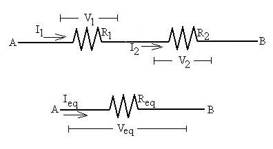
We see a current Ieq flowing into the combination, with
I1 passing through R1 and I2 passing
through
R2. By conservation of charge, we know that
Ieq= I1 = I2.
In other words, not only are Ieq, I1 and I2
equal currents, they are the same current.
Also, we know that the potential difference across the pair Veq
is the same as the sum of the individual differences across each (V1
and V2),
Veq = V1 + V2,
since the electric field is a conservative field.
Lastly, for each we can write Ohm's Relationship:
Veq = IeqReq; V1
= I1R1; V2= I2R2
So, let's start:
Veq = V1 + V2,
IeqReq = I1R1 +
I2R2.
All Is are equal, so they cancel:
Req= R1 + R2
This shows that the equivalent resistence of a series pair is greater
that either resistance by itself. This should make sense, because
the combination has more obstacles for the charges to collide with.
Here is an extremely lame analogy: Consider a theatre letting
out. The charge is represented by the patrons and the current is
the rate at which they leave the theatre. The potential is their
desire to get home. In the way is a set of turnstiles, which
limits
the current. By opening up more turnstiles (adding parallel
resistances)
the rate of exiting increases, and by placing a second row of
turnstiles
behind the first, the rate is decreased. Of course, increasing
the
desire of patrons (potential difference) to leave by yelling 'fire'
will
also increase the 'current.'
How does the concept of resistance fit into our water analogy?
If a wire is like a pipe, then a resistance is like a partial blockage
in the pipe;
it acts to decrease the flow rate (current) and causes a pressure
difference
(potential difference) to develop across itself.
Here is an additional note: Notice that the relationships for
parallel and series combinations of capacitors is the reverse
from
the relationship for combinations of resistors. There is no deep
reason for this; each of R and C is a ratio of a charge-related
quantity
(either Q or I) and potential difference, but they are defined
inversely:
R = (potential difference)/(charge-related
quantity)
C = (charge-related quantity)/(potential difference).
We could have arranged to define the conductance (S =
1/R, unit is the Siemens) instead and arrived at similar
relationships
for S and C, but since few people worry about conductance except
transistor
engineers, we don't either.
Before moving on, let's do some calculations for the resistances of
more complex shapes.
Consider a trapezoidal block of material with uniform resistivity,
length L, width W (out of the page), but a height that varies linearly
from y1 to y2>y1. Let the
prospective current flow from left to right.
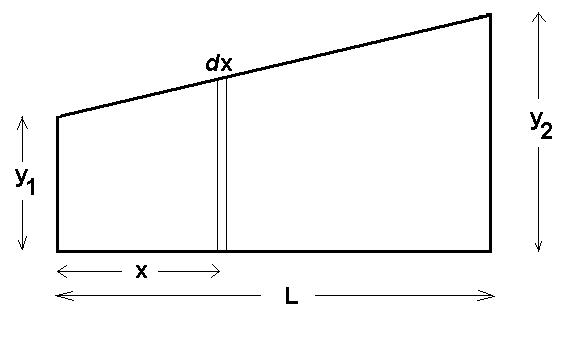
Let's break the object up into thin slices of thickness dx.
The resistance of each such slice will be
dR = rdx/A = rdx/Wy = rdx/W[y1+(y2-y1)x/L].
The total resisitance in that orientation is then the sum of all the
slices (they are in series):
R = 0 L rdx/W[y1+(y2-y1)x/L]
thsi is amenable to u substitution with u = y1+(y2-y1)x/L
and du = (y2-y1)x/L.
R = rL/[W(y2-y1)] u-1 du = rL/[W(y2-y1)]
ln u = rL/[W(y2-y1)]
ln [y1+(y2-y1)x/L] 0|L
= rL/[W(y2-y1)] ln [y2/y1]
Consider a pair of coaxial surfaces or radiuses rA and rB>rA
and length L. The space betweeen them is filled with a material
of uniform resistivity, r.
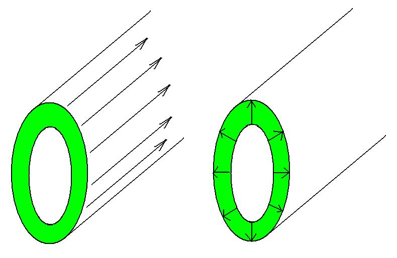
First, find the resistance of the material for a current directly along
the length.
Well, this is fairly easy because the cross sectional area is constant
along the length of the object. So,
R = rL/A = rL/[prB2
- prA2] = rL/p[rB2-rA2].
Now find the
resistance if the current were to run radially.
Break the material up into thin cylinders. Each has
cross-sectional area 2prL and thickness dr. The resistance of such a
sheet is then
dR = rdr/2prL.
The slices are in series in this case, so we simply add them up:
R = rArB rdr/2prL = [r/2pL] rArB dr/r = [r/2pL] ln(r) rA|rB
= [r/2pL] ln(rB/rA)
.
Consider an LxLxd rectangular slab of uniform resistivity. Find
the resistance from one small face to the opposite face.
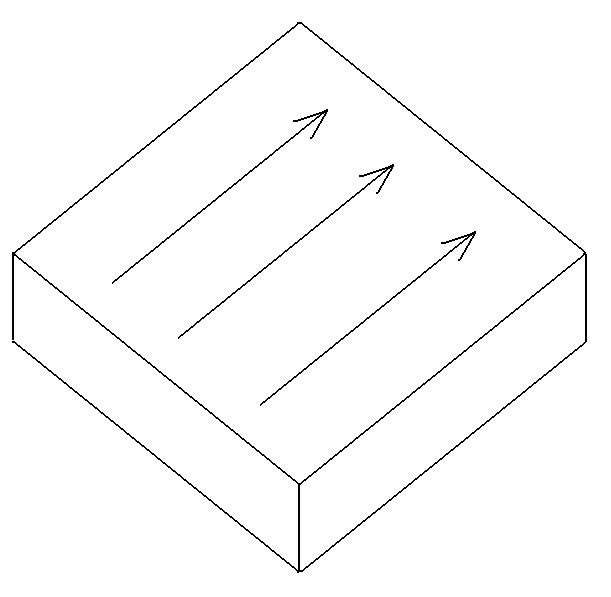
Again, the cross sectional area is constant along the length, so we
have that
R = rL/A = rL/Ld
= r/d, independent of L!
This is sometimes called the sheet
resistance and has units of Ohms per square (W/[]).
Batteries
We have been rather incautiously applying potential differences to
capacitors
and resistors. Let's discuss one device which can do this, the battery.
The classic battery is a container of acid into which are placed two
electrodes
composed of different metals (here, A and B).
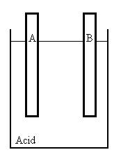
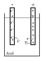
The materials are chosen so that two chemical reactions take
place.
One has the result of removing electrons from Metal B and placing them
into the acid solution, the other has the effect of placing electrons
onto
Metal A from the solution. As a result, electrode A becomes
negatively
charged while B becomes positively charged.
The symbol for a battery is:
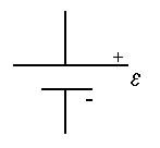
The longer line represents the positive terminal and the
shorter
line the negative terminal (makes sense, since we need twice as
much line to make a cross as a dash); here the vertical lines represent
wires connected to the battery terminals.
Why do the metals have to be different?
When does this reaction stop? There is a chemical
potential
difference which drives the electrons over to electrode A, but as A
is charged up, it gets harder and harder to place the next electron
over
there (electrostatic repulsion), and so there is a reverse electrical
potential
difference forming as well. When these two cancel each other, the
reaction stops. The electrical potential difference of the
battery
in this state is called the emf (e,
unit is volts). The letters of 'emf' do stand for words,
but
they are misleading and do not accurately describe the nature of emf;
better
to think of emf as a new word meaning the potential difference between
the terminals of a battery when this static equilibrium has been
reached.
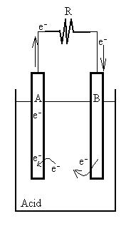
Now, connect a wire (with some small resistance) from the terminal
of electrode A to that of B. Now, the electrons have a way of
returning
to B without having to fight against the chemical potential. As
charge
is transferred on an outside path from one terminal to the other, the
electrical
potantial difference between the electrodes will decrease and the
chemical
reation will restart, resupplying charges to the terminals. So,
unlike
in a capacitor, the plates or terminals are continually resupplied with
charge.
As the charge flows, a new dynamic equilibrium will be achieved such
that the charge transfer due to the chemical reactions and the current
in the outside circuit are equal; this will occur however at a
potential
difference between the terminals (TPD) which is less than the
emf.
The larger the current through the battery, the lower this equilibrium
TPD will be.
INSERT GRAPH
Let's use the water analogy, in which water corresponds to charge
and
water depth corresponds nicely to potential difference. The
cistern
in your toilet has a valve attached to a lever with a floater; when the
water level in the tank lowers, the floater also lowers and the valve
is
opened, thus refilling the tank. Often, though not always, the
rate
at which water refills the tank is greater when the level of water in
the
tank is lower (since the valve is more open). This device
represents
the chemical reaction, since the rate of the chemical reaction will
increase
when the TPD is lower.
Now, suppose that you have a leak (current) in the tank; the water
level will sink, opening the valve, until the rate of leakage and the
rate
of refilling match (current in and out of the battery). This will
necessarily occur at a water level (TPD) lower than 'full.' If
the
leak (current) becomes larger, the equilibrium will be reached when the
water level (TPD) is even lower. Stopping the leak allows the
water
level (TPD) to return to its 'full' value (the emf).
We model this effect by assuming that there is an internal
resistance
rINT inside the battery, across which there is a potential
difference
(I* rINT) while current is flowing, such that:
TPD = e
- I rINT.
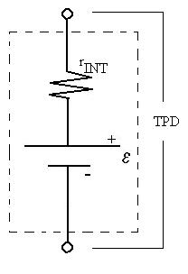
We can calculate rINT by looking at the slope of the line
in the graph above.
We find that larger batteries tend to have smaller internal
resistances,
since the larger plates inside provide more surface area for the
reactions
to take place more efficiently, and also that the internal resistance
of
a given battery tends to increase as the reactants are used up.
Remember though that there is not really such a resistor inside
batteries;
this is just a model.
Here are some questions to consider:
Batteries generally get hot while providing a current. Why?
Why do batteries 'run out?'
Why do batteries run down slowly, rather than work fine and suddenly
stop working?
What could one do to resuscitate a dead battery?
Why are some batteries non-rechargeable?
Can the TPD ever be greater than the emf?
Here is an example. Consider your car battery with an emf of
about
12.6 V. Turn on your headlights, which draw a current of about
20A.
Now, try to start your car. What happens to the headlights?
The starter of a typical car draws about 400A from the battery.
Because of this huge drain, the TPD of the battery is reduced to about
6V, and correspondingly this reduction in the potential difference
across
the lamps forces less current through them, making them dimmer.
Once
the starter is disconnected from the battery, the TPD rises back to
about
12V and the lights regain their former brilliance.
Let's consider briefly the possibility of placing batteries in
series
or in parallel; the same rules apply, of course. In series the
total
emf will be the sum of teh individual emfs, and the current will be the
same through each battery. In parallel, the total current out of the
combination
will be the sum of the individual currents, but we have to be careful
in
terms of the potential differences across each which must be
the
same; two different emf batteries in parallel will cause one to
discharge
and the other to charge. This is why mixing old and new batteries
(even of the same nominal emf) in a device is not a good idea.
Kirchhoff's Rules
Some arrangements of resistors (and of other components) are not so
amenable
to the reduction treatment outlined above. For those, we need to
use a more powerful, if more tedious method, now known as Kirchhoff's
Rules. These are restatements of the same two concepts
discussed
previously: conservation of charge and the fact that the electric field
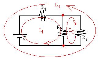
is conservative. As we work through Kirchhoff's Rules, let's
consider
a simple concrete example, simple enough that we need not even use the
rules to find the currents and potential differences.
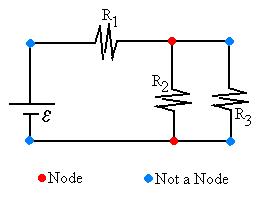
Consider a node, a spot where there is a choice of
directions
to go in a circuit. Some books define a node as a spot where two
wires are connected, but some students invariably have problems with
distinguishing
nodes from bends in a wire.
Mark all of the nodes in the circuit. Here, we see that there
are two nodes.
Next, we shall look first for the branches of the
circuit.
A branch is any path which connects two nodes without passing through
any
other node.
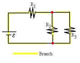
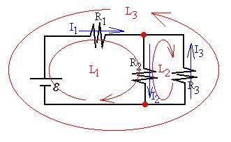
Here, we see that there are three branches. Each branch carries
a current, Ii. We have at this time no idea even in
which
directions the currents are flowing, but the beauty of Kirchhoff's
rules
is that everything will work out in the end; if we guess a current
direction
incorrectly, we shall merely obtain a negative answer. Assign
currents
to each branch (I1, I2, et c.) along with
a direction for each (indicated on circuit diagram with arrows).
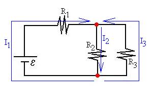
Note that the current is I1 in all of the first
branch,
that is, before, after, and through the battery.
Conservation of charge indicates that the sum of all currents
entering
a node must equal the sum of all currents leaving a node, else charge
would
be either created or destroyed.
Si (Iin)i
= Sj (Iout)j
I would prefer to write this differently. Let's say that the
sum of all currents entering a node is zero, but make those actually
entering
be counted as positive, and those currents actually leaving the node be
negative ('negative in' = 'out,' right?):
Si (Iin)i
= 0
These equations may look very different, but remember that they are
simply based on different bookkeeping methods. In this example,
we
would write:
top node: I1 - I2 + I3 = 0,
bottom node: - I1 + I2 - I3 = 0.
Notice the redundancy of the two equations; the second one gives us
no additional information over the first one, and so we can ignore
it.
This is discussed in more detail below.
Now let's look at the potential difference we encounter as we trace
a loop around the circuit; a loop is a closed path around the
circuit.
Because of the fact that the electric field is conservative, the work
we
do moving some test charge completely around the loop back to its
starting
place must be zero. So, then, the sums of all the potential
differences
we encounter while doing this must add to zero; some will be increases
in potential and others must be decreases in potential:
Si DVi
= 0.
These potential differences will be of two types (for now): the emfs
of batteries and potential differences across resistors. I prefer
to count these two types separately by summing the voltage rises across
the batteries (a drop would be counted as a 'negative rise') and the
drops
across the resistors. Since I will put these two types of terms
on
opposite sides of my equation, the sign problem will be accounted for:
Si Ri Ii
= Si ei
What sign should be assigned to each term? For resistors, current
always flows from higher potential to lower potential, so it seems that
if I traverse the resistor with the current, I should count that as a
positive
drop, and if I cross the resistor against the current, that would be an
increase in potential or a 'negative drop,' and I should insert a minus
sign. If I cross the battery from the negative terminal to the
positive
terminal, that would be an increase, so I stick a plus sign in front of
it, but if I cross it the other way, that's a decrease and I should
insert
a negative sign. Note that the sign given to a battery emf does not
depend
on the direction of the current though it.
Let's look at out example. How many loops are there?
Note that it doesn't matter which way we travel around a loop, since
drops will become rises and rises drops, and we'll end up with the same
equation in the end. Let's write the loop rule for each of the
loops
shown in the figure:
L1: + R1I1 + R2I2
= +e [We
traverse
R1 and R2 with the respective currents, and we
cross
the battery from low to high potential.]
L2: - R2I2 - R3I3
= 0 [We traverse R2 and R3 against
the
respective currents.]
L3: -R1I1 + R3I3
= -e [We
traverse
R1 against the current and R3 with the current,
and
we cross the battery from high to low potential.]
We notice that the third equation can be obtained by adding the first
and the second then multiplying by negative one, and so it gives us no
new information and we therefor ignore it (more on this later).
So, we have three equations which we can use to solve for three
unknown
currents:
|
I1 |
+ |
- |
I2 |
+ |
|
I3 |
= |
0 |
| R1 |
I1 |
+ |
R2 |
I2 |
|
|
|
= |
+e |
|
|
|
- R2 |
I2 |
+ |
- R3 |
I3 |
= |
0 |
Generally, at this point the math gets really ugly, even for so simple
a circuit.
Multiply the first equation by R1and subtract it from the
second equation:
| R1 |
I1 |
+ |
-R1 |
I2 |
+ |
R1 |
I3 |
= |
0 |
| R1 |
I1 |
+ |
R2 |
I2 |
|
|
|
= |
+e |
to get:
| (R1 + R2) |
I2 |
- |
R1 |
I3 |
= |
+e |
Now multiply this equation by R3 and the third of the
original
equations by R1,
| (R1 + R2)R3 |
I2 |
+ |
- R1R3 |
I3 |
= |
+R3e |
| - R1R2 |
I2 |
+ |
- R1R3 |
I3 |
= |
0 |
and subtract to get
| (R3(R2 + R1) +
R1R2) |
I2 |
= |
+R3e |
or that
I2 = R3e/[R1R2
+ R2R3 + R2R3].
Substituting this back into the third of our original equations gives:
I3 = -[R2/R3]I2 = -[R2/R3]R3e/[R1R2
+ R2R3 + R2R3] = -R2e/[R1R2
+ R2R3 + R2R3].
The negative sign indicates that we guessed the direction of I3
incorrectly and that it actually flows in the opposite direction, as we
would expect from looking at the circuit.
Now, substitute these values for I2 and I3 back
into a previous equation to find I1:
I1 = I2 - I3 = R3e/[R1R2
+ R2R3 + R2R3] - - R2e/[R1R2
+ R2R3 + R2R3] = [R2+
R3]e/[R1R2
+ R2R3 + R2R3].
Now, in this particular case, it would have been easier to use
reduction
to find the equivalent resistance, but this was a good exercise.
Some systems can not be solved with reduction. Also, in this
case,
we assumed that we knew the emf and the resistances and were looking
for
the currents, but we could just as easily have known one current and
not
known one resistor value, et c., so long as we have an equal
number
of independent equations and unknown variables (Note, mathematically,
other
conditions have to be met, but since we assume that there is only one
physical
solution for a system like this, that condition suffices).
In general, how many of each type of equation (loop and node) do we
need in order to solve a problem? We find that if we have N
nodes,
we need N-1 node equations, since the last node equation will be some
combination
of the others and it therefor presents no new information. If
there
are M small loops in the circuit, then we need M loop equations.
Again, any more past that number will be combinations of the others and
we shall learn nothing new about the circuit from them.
Generally,
we know all the Rs and es,
and are asked to find the Is. We can double check our
information,
since the rule is that we need Z equations to find Z unknowns.
You
should find that M + N - 1 is equal to the number of branches in the
circuit,
and therefor also equal to the number of currents we need to find. The
rest is just algebra.....
So, consider this generic example:
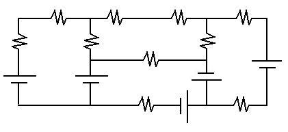
How many nodes are there?
How many loops?
How many independent loops?
How many branches?
How many of each equation type should we write to solve this problem?
There is a Kirchhoff's Rules Solver on the course Excel
Workbook. This will determine up to six currents (and other
quantities
with some imagination). Just write the (M+N-1) equations and
place
the co-efficients in the correct cells. Below is an example of
how
the worksheet should be filled in with the co-efficients for the
example
done above with R1 = 20W, R2
= 30W and R3 = 50W,
and e = 14V:
|
I1 |
+ |
- |
I2 |
+ |
|
I3 |
= |
0 |
| 20 |
I1 |
+ |
30 |
I2 |
|
|
|
= |
+14 |
|
|
|
- 30 |
I2 |
+ |
- 50 |
I3 |
= |
0 |
KIRCHHOFF'S RULES SOLVER
| 1 |
I1 + |
-1 |
I2 + |
1 |
I3 + |
0 |
I4 + |
0 |
I5 + |
0 |
I6 = |
0 |
| 20 |
I1 + |
30 |
I2 + |
0 |
I3 + |
0 |
I4 + |
0 |
I5 + |
0 |
I6 = |
14 |
| 0 |
I1 + |
-30 |
I2 + |
-50 |
I3 + |
0 |
I4 + |
0 |
I5 + |
0 |
I6 = |
0 |
| 0 |
I1 + |
0 |
I2 + |
0 |
I3 + |
1 |
I4 + |
0 |
I5 + |
0 |
I6 = |
0 |
| 0 |
I1 + |
0 |
I2 + |
0 |
I3 + |
0 |
I4 + |
1 |
I5 + |
0 |
I6 = |
0 |
| 0 |
I1 + |
0 |
I2 + |
0 |
I3 + |
0 |
I4 + |
0 |
I5 + |
1 |
I6 = |
0 |
|
|
|
|
|
|
|
|
|
|
|
|
|
| I1 = |
0.361 |
I2 = |
0.226 |
I3 = |
- 0.140 |
I4 = |
0 |
I5 = |
0 |
I6 = |
0 |
|
A Further Note for Those
Who
Care
If one were to try to work out the assertions made in this paragraph in
detail, one would probably fail. The reason is that the whole
story
has not been presented. One might say the following:
L is doubled, so for constant DV, the E
field is halved.
E is halved, so the force FE = qE is halved and the
acceleration
a = F/m is halved.
The electrons are assumed to start from rest after each collision and
accelerate against the field until the next collision with a scattering
site, perhaps a distance d away. Using the kinematic equations
from
previous discussions, one sees that vAVE = 1/2
vf = 1/2 [2ad]1/2,
so
that the average velocity does not halve when the acceleration
halves.
The resolution to this problem is in the details of the motions of
the
electrons. When the electric field is zero, the electrons are not
motionless,
but actually moving very quickly. The fact that the current in
this
situation is zero only means that just as many electrons are flying in
one direction as in the opposite direction, so that there is no net
movement
of charge. In fact, in a metal, the conduction electrons are
bouncing
around inside the metal in much the same way as gas molecules in a box
do. One can even use the results of the equipartition of
energy
theorem to estimate the rms speed:
1/2m vrms2 = 3/2kBT;
at room temperature, vrms = 105 m/s, compared to
the asserted average drift speed of the current, ~10-4
m/s.
The point here being that the quantity which is constant is the time
between collisions, not the distance traveled between collisions.
So the relationship one should consider is
(vDrift)AVE = 1/2 (vDrift)
f
=
at/2,
so that the average drift speed of the motion against the electric
field which is superimposed on the random motion is indeed proportional
to the acceleration and so also to the electric field.
Let's back up a little bit: how do we know that the drift speed is
so
low? Consider a typical metal wire with cross sectional area 1mm2
carrying 1A of current. In one second, 6x10¹⁸
electrons
will pass a given point. These electrons on average occupy the
same
volume that their 'host' atoms do; since metal atoms are typically
separated
by about 3Ao = 3x10⁻¹⁰m, the total volume
occupied
by the electrons will be 6x1018*[3x10-10]3
= 1.6x10⁻¹⁰m3. Given that the
cross-sectional
area of the wire is 10-6m2, the electrons must
then
move at 0.16x10⁻³ m/s or as stated at about 0.1 mm/s.
Continue
on to the Next Section
Return
to the Notes Directory
D Baum 2001