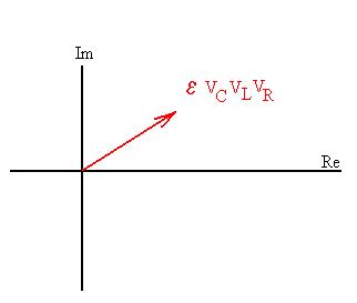
Compare this situation with that for the series LRC circuit;
the approach is the same but the details are different. Now, we
realize
(Kirchhoff's Loop Law) that the voltage drops across each element must
be equal to the emf of the source:
e = VL =
VC = VR.
From the Node Law, we can say that:
ITOT = IR + IL + IC.
The relationships between the current s and voltage drops across each
individual component are the same as before.
Construct a phasor diagram.
The current through the resistor is in phase with VR, the
current through the inductor lags 90o behind VL,
and the currnt into the capacitor leads VC by 90o.
Draw these in.
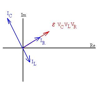
The total current from the power supply is the phasor sum of these
currents:

So, we can write that
(ITOT)max = [IRmax2 + (ICmax
- ILmax)2]1/2.
Now substitute and try to get something that looks like Ohm's
relationship,
emax
= Z Imax
:
(ITOT)max = [IRmax2 + (ICmax
- ILmax)2]1/2 = [(VRmax/R)2
+ (VCmax/cC - VLmax/cL)2]1/2
= [(emax/R)2
+ (emax/cC
- emax/cL)2]1/2
= emax [1/R2
+ (1/cC - 1/cL)2]1/2
= emax [1/R2
+ (wC - 1/wL)2]1/2
.
Comparison of this result with the Ohm's law like relationship above
suggests that
Z = [1/R2 + (wC - 1/wL)2]
-1/2
.