Section 2-3 - Capacitors, Capacitance, and Dielectrics
Capacitors & Capacitance
Parallel Plate Capacitors
Dielectrics
Energy Stored in a Capacitor
Combinations of Capacitors
Correlation
to
your Textbook
Capacitors & Capacitance
A capacitor can be defined as an device to store charge.
Usually,
while storing the charge, it also stores energy. Here is a very
simple
example: consider an initially uncharged metal sphere of radius
R.
Let's bring a very small bit of charge from infinity to the metal,
where
it will of course reside on the surface. Now, the sphere is
slightly
charged. To bring the next bit of charge up from infinity, some
work
must be done to overcome the repulsion it experiences due to the first
bit of charge. The third bit of charge will require even more
work,
et
c. This energy is stored as the electrical potential
energy of the charges. Accordingly,
the electrical potential at the surface of the sphere increases, as
well.
The ability of a capacitor to hold charge is characterized by the
capacitance,
C. Specifically, we say that the capacitance is the amount of
charged
transferred on the capacitor per volt of potential difference:
C = Q/V.
The unit of capacitance is the farad (F), named after Michael
Faraday (The faraday was already a unit used by chemists).
What, then, is the capacitance of the metal sphere described above?
Once charged, the potential field caused by the charge will look like
that of a point charge: V = keQ/r. At the surface of
the
sphere (where r = R), the potential will then be V = keQ/R,
where we define the potential at infinity to be zero. Then,
C = Q/V = Q/[keQ/R] = R/ke.
Note that we generally (but not necessarily) think of capacitors as
having two plates, with the charge taken from one and placed on the
other.
In this example, one might consider the second plate to be located out
at infinity.
Parallel Plate Capacitors
Let's look at a very special type of capacitor, the parallel plate
capacitor.
This comprises two flat, parallel, probably metal, sheets of area A
separated
by a relatively small distance d. Let's transfer a charge Q from
one plate to the other, causing a potential difference V; now one plate
has charge +Q and the other -Q. We can, if we like, talk about
the
charge per unit area, s = Q/A. From
this,
we get the notion that each plate resembles to some degree an infinite
sheet of charge like those discussed in the Gauss's
Law section of the notes; we can get away with this if the
separation
of the plates is small compared to the length of a side. In that
case, the positive sheet creates an electric field of magnitude E+
= s/2eo
outward, while the negatively charged sheet produces a field of
magnitude
E- = s/2eo
inward. In the region between the sheets, these fields will add
to
give a total field of E = s/eo,
and in the outer regions, the fields will cancel.
Let's look at the definition of capacitance again:
C = Q/V.
Do some substitution, remembering that E = (-)DV/Ds(here
Ds
will be the distance between plates, d):
C = Q/V = sA/V = sA/Ed
= sA/(s/eo)d
= eoA/d.
We see that the capacitance of a parallel plate capacitor
depends
only on the dimensions of the capacitor, plus some constant that
makes the units work out. For different configurations,
the specific result will be somewhat different, but still based on the
dimensions only. The nice result is that, for a situation such as
this, the capacitance of the capacitor is a constant regardless of the
amount of charge it holds. This is not always true; special
capacitors
have been built with new materials from which C can vary with an
additional
applied voltage.
Here's another example. Calculate the capacitance
of two concentric cylinders of radiuses R1 and R2
and length L. Assume that L is long compared to the radiuses.
If the cylinders are long, we can make use of the expression for the
electric field we found in the previous section (assume the inner
cylinder R1 is positive)
E = 2kel/r.
DV = - R1 R2
E.dr
=
- R1R2
2kel/r dr
= - 2kel ln[R2/R1].
Ignore
the negative sign for now; it indicates that the potential is
lower on the outer cylinder .
R2
E.dr
=
- R1R2
2kel/r dr
= - 2kel ln[R2/R1].
Ignore
the negative sign for now; it indicates that the potential is
lower on the outer cylinder .
Then, C = Q/DV = lL/[2kel
ln[R2/R1]] = L/[2ke
ln[R2/R1]].
This result again depends only on the dimensions of the capacitor.
Let's go back to out original example, but let's have two spheres of
radiuses R1 (inner) and R2 (outer). The
field is
E = keQ/r2.
Then,
DV = - R1R2
E.dr
=
- R1R2 keQr-2dr
= keQ[1/R2 - 1/R1] (which is again a
negative number).
Ignore the negative sign for now; it indicates that the potential is
lower on the outer sphere.
Then, C = Q/DV = Q/[keQ[1/R1
- 1/R2]] = R1R2/ke[R2
- R1]
In the parallel plate and coaxial cylinder examples, we assumed that
the E-field was uniform (first
case) or radial (second example). However, when you mapped out
the electric field for aprallel plates in your lab exercise, you found
that the field bulged out near the ends of the plates. These edge effects can be neglected if
the plate separation is small.
Dielectrics
We recall a discussion about the effects of an electric field on
metals;
the external field casues the charges inside the metal to re-distribute
themselves (thus causing an internal field) until the total internal
field
is zero. Here, we introduce materials known as dielectrics.
In these materials, the electrons are not as free to move about as
those
in metals, and so the external field is not completely cancelled,
resulting
in not a zero net field, but a reduced net field. The degree to
which
the material reduces the field is characterized by the dielectric
constant,
k,
such that
E = EEXT/ĸ.
What is the dielectric constant of vacuum?
In a very naive sense, what might one say is the dielectric constant
of a metal?
How does the dielectric affect the capacitance of a capacitor?
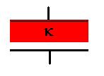
Insert a slab of dielectric material into the gap between the plates of
a parallel plate capacitor, filling the space completely. Repeat
the calculation above. Then,
C = Q/V = sA/V = sA/Ed
= sA/(EEXT/k)d
= ksA/(s/eo)d
= keoA/d = k
Co
That is, the dielectric material increases the capacitance by a factor
k.
Although we just did this for a parallel plate capacitor, the result is
the same for any shape, since E
is reduced by factor k, so then so is DV, and so C is incresed by factor k.
LAB EXERCISE: Find the dependence of capacitance on plate area and
plate separation for a parallel plate capacitor.
Energy Stored in a Capacitor
When we spoke about transferring the charge from one plate to the
other,
we mentioned that very little if any energy was required to move the
very
first electron, but that slightly more was necessary for the next,
since
we need to pull it away from now positive plate and force it onto the
other
plate, which is now negatively charged. In fact, each
additional
charge we transfer will be harder to move than the preceeding
one.
Let's see if we can calculate how much total work is necessary to
charge
up a capacitor.
First, regard the figure, which shows the relationship between the
charge transferred and the potential difference between the plates:
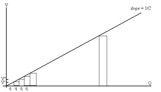
The first q is transported against a zero potential difference, so
no work is done, and no energy is stored. However, in the
process,
the potential difference is raised to V'. When the next q is
transported,
work qV' is done. This is represented by the area contained by
the
small rectangle. When the next charge q is moved, it's moved
against
a potential difference of V", and the work required is qV", once again
represented by the area inside that rectangle. Once we
move
the last charge (at potential V, for a total of Q), the total work
should
be the sum of the areas of all the rectangles. If we make the
size
of the charges we moved smaller and smaller, and consequently, the
number
of them moved larger and larger, the sum of the rectangles' areas
should
be very close to the area under the triangle,
Wtotal = 1/2(base)(height) = 1/2(Q)(V).
Since work is a transfer of energy, we see that there is now energy
stored in the capacitor.
UC = 1/2(Q)(V) = 1/2Q2/C
=
1/2CV2.
Alternatively, we can use calculus:
UC = W = 0Q V(q) dq = 0Q [1/C]q dq = 1/2q2/C
0|Q = Q2/2C, as
before.
Another quantity that is often considered useful is the energy density, ηE.
Consider
the parallel plate capacitor (and ignore edge effects).
The energy stored in the capacitor is 1/2CV2.
The
volume of the capacitor is Ad. The energy per unit volume is then
ηE = 1/2CV2/Ad = 1/2[eoA/d]V2/Ad = eoV2/2d2 = 1/2
eoE2.
The idea here (which I personally don't care for) is that the
electric field itself possesses some energy. It's sometimes
useful.
Combinations of Capacitors
Consider two capacitors connected as shown:
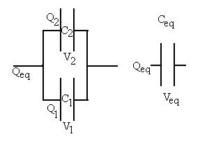
We want the equivalent capacitor on the right to do the same job as
the combination on the left: store the same amount of charge Qeq
with the same applied potential difference Veq. What
do
we know? By conservation of charge, we know that
Qeq = Q1 + Q2,
since that charge is split between the two capacitors as it is sent
in from the left/taken off to the right.
We can also say that
Veq = V1 = V2,
since the potential is related to the work done taking a test charge
from one side of the combination to the other, and since the electric
field
is a conservative field, that work must be independent of the
path
taken.
| Delving into this a little more deeply, when everything is in
equilibrium,
the metal wires are equi-potential surfaces, so if the left hand side
of
the capacitor's wire is at potential VA, then every spot on
that wire and the plate itself is also at potential VA.
The
same is true for the other end, which we might say is at potential
VB; every point on the right side wire and the right hand
plate
is at potential VB. Yet another way of looking at it
is
that, inside a metal at equilibrium, the electric field is zero, and so
no work is necessary to move a test charge from the end of the wire to
the plate. So, in review, all of the potential drop is across the
plates of the capacitor (once equilibrium is reached). |
In addition, we know from the definition of capacitance that:
C1 = Q1/V1, C2 = Q2/V2,
and
Ceq = Qeq/Veq.
Now, we start substituting:
Qeq = Q1 + Q2
CeqVeq = C1V1 + C2V2
But, all the Vs are equal, so we can cancel them out:
Ceq = C1 + C2
Here is our result: the equivalent capacitance should be the sum of
the original two capacitances. Incidently, this is referred to as
a parallel arrangement of capacitors. For more than two
such
capacitors, just continue to add terms.
Does this make sense? Try a simple example:
Suppose that we take two identical capacitors Co and connect
them as shown above. The relationship we just derived indicated
that
the equivalent capacitance is Co + Co = 2Co.
But,
we could just as well have connected them +plate to +plate and -
plate
to - plate without the wires:
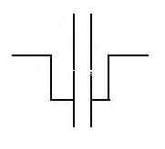
in which case, we'd have a single capacitor of spacing d, area 2Ao,
and
therefor capacitance eo(2Ao)/d
=
2Co, as expected.
Let's try an different arrangement:
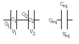
In this case, we can say that Q1 = Q2 = Qeq,
since
all of the Qeq we put on the capacitors from the left
will end up on the left plate of C1, and the Qeq
we take off to the right will all come from the right plate of C2,
making
it possess charge -Qeq. We expect that the
right
plate of C1 will then have a charge -Qeq
attracted
to it by the other plate's positive charge, and that will leave behind
charge +Qeq on the left plate of C2. In
addition,
we can say that Veq = V1 + V2, again
because
the electric field is conservative. Also once again, we know by
definition
that
C1 = Q1/V1, C2 = Q2/V2,
and
Ceq = Qeq/Veq.
So start substituting:
Veq = V1 + V2
Qeq/Ceq = Q1/C1 + Q2/C2
But, all the Qs are equal, so cancel them:
1/Ceq = 1/C1 + 1/C2 ,
which is the result for series capacitors. For additional
series capacitors, just continue to add reciprocal terms.
What if there is a combination of parallel and series
arrangements?
Look for small groupings on one type or the other and reduce them
first.
Then combine those simplified equivalent capacitors with it neighbours
until only one capacitor is left (or at least until the system is
simple
enough to determine the answer to your problem).
Try some examples:
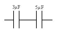
What is the equivalent capacitance of this combination?
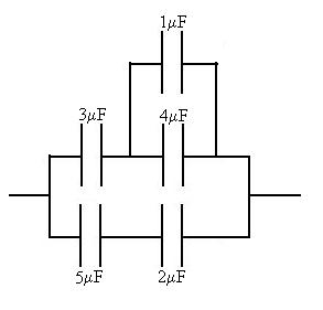
What is the equivalent capacitance of this combination?
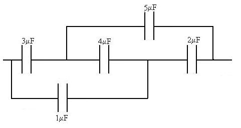
What is the equivalent capacitance of this combination?
Lastly, let's look at a particular example, more as a warning than
anything else. Consider two identical capacitors, C, of which one
has charge Qo and potential difference Vo and the
other of which is uncharged. The total energy of this system is
then
(UC total )o = Qo2/2C +
0 = Qo2/2C.
After the capacitors are connected, each will have (we won't work this
out explicitly here) charge Qo/2, and energy [Qo/2]2/2C
=
Qo2/8C, and the system will have total energy
(UC total )f = Qo2/8C +
Qo2/8C = Qo2/4C.
Note then that a naive application of conservation of energy to solve
this problem would not work! Where did the missing energy go?
In the second case mentioned, will more energy be lost than in the
first case?
Additional Examples
Consider a parallel plate capacitor (area A and splate separation d)
that is half filled with a dielectric k.
What
is the capacitance?
Treat this as a parallel combination. CTOT = Cdielectric
+ Cair = keo(1/2A)/d
+
eo(1/2A)/d
= [1 + k] eoA/2d.
What if the dielectric were arranged the other way? Let's let the
dielectric occupy 3/4 of the volume between the plates.
Two ways to do this (which are ultimately identical). First,
let's slap a thin sheet of metal on the exposed face of the
dielelctric. That makes two capacitors in series, and the total
capacitacne should be:
1/CTOT = 1/Cdielectric + 1/Cair = 1/[keoA/(3/4)d]
+
1/[eoA/(1/4)d]
=
3/4d/keoA + 1/4d/eoA = 3/4d/keoA + 1/4dk/keoA = [3+k]d/
4keoA
So, CTOT = 4keoA/[3+k]d.
More directly,
Assume there's a charge +/- Q on each plate. The field where
there is no dielectric is E = s/eo. The field where there is
dielectric is E = s/keo.
The potential difference betweet the plates is then
DV = - 03d/4
E.dr - 3d/4d
E.dr
= - 03d/4 s/keo
dr - 3d/4d
s/eo dr
= - 3ds/4keo - ds/4eo = - 3ds/4keo
- dks/4keo
=
-[3 + k]ds/4keo = -[3 + k]dQ/A4keo =
Drop the minus sign. Then
C = Q/DV = Q/[[3 + k]dQ/A4keo]
= QA4keo/[[3 + k]dQ] = 4keoA/[[3 + k]d] .
Note that if we let k -> 1 (i.e. the capacitor is empty), then
we get back our original result of eoA/d.
Two more examples...
Consider a coaxial capacitor filled with two dielectrics. The
inner conductor has radius a, dielectric 1 fills the space from a to b,
then dielectric 2 fills the space from b to the outer conductor at c.
We've seen previously that the capacitance of an empty coaxial
capacitor is
C = L/[2keln(R2/R1)]
We can consider this to be two series capacitors:
CInner = k1L/[2keln(b/a)]
and
COuter = k2L/[2keln(c/b)]
1/CTotal = 1/CInner + 1/COuter
= 2keln(b/a)/k1L
+
2keln(c/b)/k2L = [2ke/k1k2L][k2ln(b/a) + k1ln(c/b)]
So, CTOTAL = [k1k2L/2ke]/[k2ln(b/a) + k1ln(c/b)].
Consider a parallel plate capacitor with plate separation d, and plate
dimensions W and L. The space between the plates is filled with
two dielectric materials, as shown:
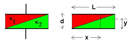
Find CEQ.
Divide the capacitor up into narrow strips of width dx. Let x be the distance
from the left end. The thicknesses of the two dielectric layers
are then y and d-y, where y = (d/L)x.
Each of these mini-capacitors has capacitance
dCUPPER = k1eoWdx/(d-y) and dCLOWER = k2eoWdx/y.
These two capacitors combine in series:
1/dC = 1/dCUPPER + 1/dCLOWER = (d-y)/k1eoWdx
+
y/k2eoWdx = k2(d-y)/k1k2eoWdx + k1y/[k1k2eoWdx]
=
[k2(d-y)
+
k1y]/k1k2eoWdx
So,
dC = k1k2eoWdx
/[k2(d-y)
+
k1y] = k1k2eoWdx /[k2d
+
(k1-k2)y]
=
k1k2eoWdx
/[k2d
+
(k1-k2)(d/L)x]
=
k1k2eoWdx
/d[k2
+ (k1-k2)(x/L)]
Now, we want to add up all of these slices that are in parallel:
CTOT = 0L k1k2eoWdx
/d[k2
+ (k1-k2)(x/L)]
This is amenable to u substitution with u = k2
+ (k1-k2)(x/L)
and
du = (k1-k2)(dx/L).
This results in
CTOT = [k1k2eoWL
/d(k1-k2)] ln [k2
+ (k1-k2)(x/L)]
0|L = [k1k2eoWL
/d(k1-k2)] ln [k1/k2].
Note that this will work regardless of which dielectric constant is
larger.
For fun, you can try to show that if k1
and k2 are equal, this reduces
to keoA/d.
HINT:
you'll need a Taylor's expansion for the ln term.
Continue to Next Section
Return to Notes Directory
D Baum 2001- 2009