If the light is seen for any speed of rotation, then the speed of light would be what?
Aristotle concluded that light travels infinitely fast, based on the observation that, when one turns on a lamp, the reflection in a mirror appears immediately. Some describe this as there being no 'echo,' no delay between the light which took a direct path to our eyes and that which was reflected from the mirror.
The first scientific attempt to measure the speed of light was performed by Galileo, who took a lamp to the top of a hill, while his assistant did the same on a different hill. Galileo uncovered his lantern, the assistant uncovered his when he saw Galileo's light, and Galileo measured the time from when he uncovered to when he saw his assistant's light. This experimental technique is still used today and is called a time-of-flight measurement. Unfortunately, Galileo was only measuring human reaction times.
The next advance was made by Roemer, who observed slight discrepancies in the time between the eclipses of Jupiter's moons. He concluded that the increase in the period was due to the earth moving in its orbit away from Jupiter, and decreases in the period were due to the earth approaching Jupiter, such that the extra time was that necessary for the light to cross the orbit of the earth, and that the speed of light was therefor not infinite. Huygens used these data and arrived at a value of about 2.3 x10⁸ m/s (the size of the earth's orbit was not well known, then).
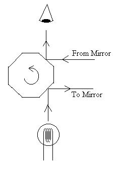
In 1849, Fizeau used a toothed wheel, and later Michelson used a
rotating
mirror apparatus, to determine that the speed of light was about
3x10⁸
m/s. The idea is that light from a bulb is reflected to a
mirror
some thirty-five km away when the mirror is in the position shown
in
the
figure. After completing the round trip, the mirror must
have
rotated
45o so that a different face reflects the light to the
observer's
eye.
If the light is seen for any speed of rotation, then the
speed
of light would be what?
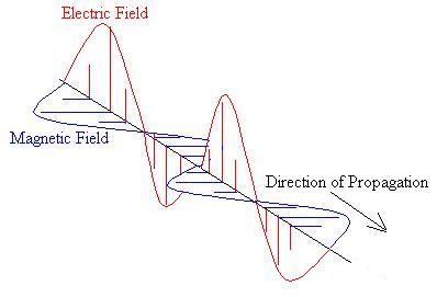
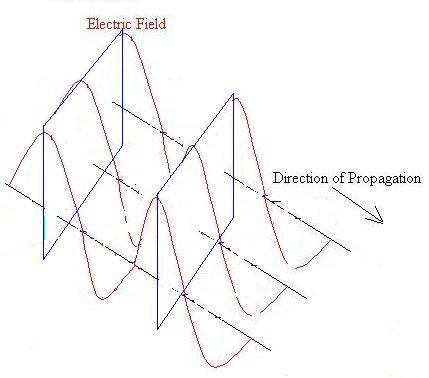
However, by the turn of the ninteenth century, the wave view of the nature of light regained support when Young explained interference and diffraction effects in terms of waves; these effects simply can not be explained in terms of a particle model. By mid-century, Foucault had shown that Newton's explanation of refraction was based on false assumptions, and Maxwell (1860s) combined Gauss's Law, Ampere's Law, and Faraday's Law to predict the existence of electro-magnetic waves with an expected velocity equal to the known speed of light; the implication seems clear: light is an electromagnetic wave.
In the 1880s, Hertz used a spark-gap to produce
electro-magnetic
waves of a type we now call radio waves; he demonstrated
that
such
waves exhibit all of the behaviours of light, such as reflection,
refraction,
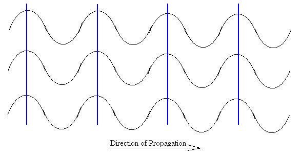
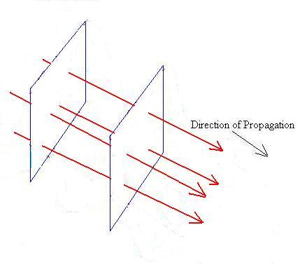
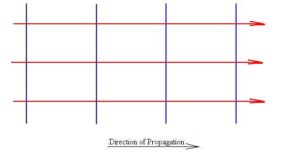
polarization,
and diffraction, and so he surmised that
1) radio waves are EM waves,
2) light behaves in the same manner as radio waves,
3) therefore, light is an EM wave.
Interestingly, Hertz's experiment, which confirmed the wave nature
of light, also exhibited different results when conducted with or
without
the room lights on, a behaviour which could not be explained with
the
wave
model and which we now call the photo-electric effect.
Einstein
was
able to explain this effect, but by using a particle-like model
for
light; these particles are called photons. It was
left to
the more mature outlook of the twentieth century to reconcile
these two
models; we say now that light is neither wave nor particle, but
that it
exhibits some behaviours of each.
For now, let us consider light to be a wave.
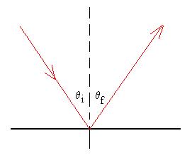
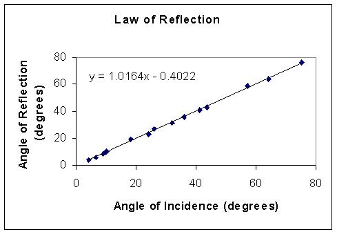
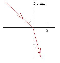
Here are some experimental results comparing the angles of
incidence
and reflection (2001/2 class):
This property could be explained with either the corpuscular or
wave
theories of light. A ball hitting a wall in an elastic
collision
and without spin will rebound at an angle equal to the incident
angle
because
of conservation of momentum.
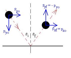
The momentum in the x direction will remain unchanged, and the
momentum
in the y-direction will completely reversed, and so qr
=
qi.
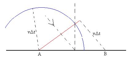
For waves, we first need to discuss Huygen's
Principle, which states that every point on a wave front
can be
considered
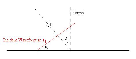
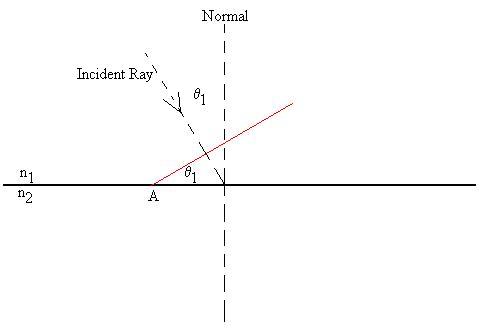
to be a point source for new waves. Then, we consider a
ray (with
its corresponding perpendicular wavefront) incident at speed v
on a
flat
surface at angle q1 as
shown. The edge of the wavefront has just reached Point
Aat time
t1:
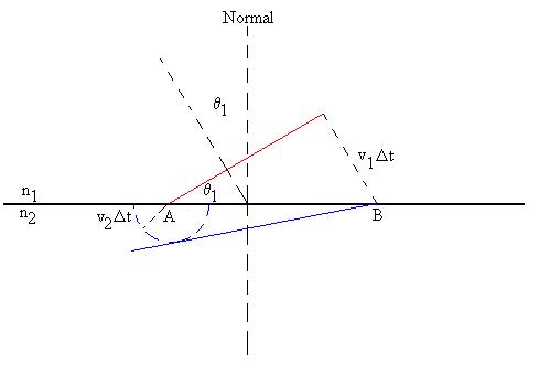
According to Huygen's Principle, Point A
will
be the source for new waves (Of course, so will many other
points on
the
surface as well, but we'll consider only what happens at Points
A &
B). Consider the same wavefront a time Dt
later, during which time the wave has moved such that the other
edge of the wavefront has arrived at Point B. The distance
that
edge
has moved in the interval is vDt.
Now
according to Huygen's Principle, Point B is a source for new
waves.
The wave created at B has not yet had any chance to go anywhere,
but
the
wave from Point A (shown in blue) could be anywhere on a circle
of
radius
vDt centred on Point A.
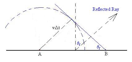
The reflected wavefront has to meet two
conditions:
first, it must be tangent to the circle we drew around A, since
it must
be perpendicular to its direction of motion away from A, and it
must
pass
through B. We can then also generate a ray indicating the
direction
of the reflected light. Through some geometry, we knw that
the
angle
at Point B is equal to the angle of reflection, qr.
Now, we have two right triangles which share a common hypotenuse
(between
Points A & B) and which each have a side of length vDt.
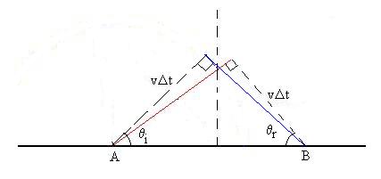
These triangles are therefor congruent, and the angles at Points A
and B are equal. So, too, then are the angles of incident
and
reflection.
Another point
of
view is Fermat's
Principle
of Least Time, which states that light will take the path
from one
point to another which requires the least time (Strictly
speaking, this
is a special case of a principle used in mechanics, where the
actual
statement is that the time is at an extreme.). Consider two
points, A
and B. Light travels from Point A to Point B after
reflecting off
a mirror along the x axis. Let x represent the spot at
which the
reflection occurs.
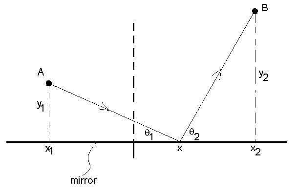
The shortest time in this case also means the shortest
distance.
For given reflection point x, the distance travelled by the
light will
be:
D = [y12 + (x1 - x)2]1/2
+ [y22 + (x2
- x)2]1/2
Then set dD/dx = 0
1/2[y12
+ (x1 - x)2]-1/2[2(x1 -
x)(-1)]
+ 1/2[y22 + (x2
- x)2]-1/2[2(x2 - x)(-1)] =
0
-
[y12 + (x1 - x)2]-1/2(x1 - x) = [y22 + (x2
- x)2]-1/2(x2 - x) = 0
cosq1 = cosq2
q1 = q2
We should of
course go back and take the second derivative to show that this
corresponds to a minimum.
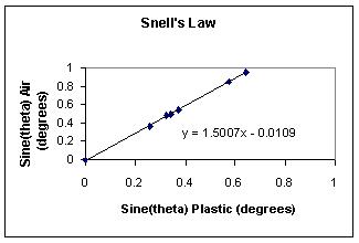
Here are some experimental
results
comparing the sines of q1
and
q2
for an air-plexiglas interface (class of 2001/2). The
line's
slope
represents nPlexiglas:
We now know that this effect is caused by the fact that light has
different
speeds in different materials, or in different parts of the same
material
(see derivation below). Remember (from above) the wave
equation,
where we saw that the speed of light (in vacuum) was given by
c = 1/[eomo]1/2.
Think back to the effect of the insertion of a dielectric of
constant
k
into
a capacitor:
Cdiel = keoA/d.
So, if the light wave were to travel through a material with
dielectric
constant k, we would expect to have to
modify
our velocity result accordingly:
v = 1/[keomo]1/2
= c/k1/2,
that is, the light slows by a factor n = k1/2,
so that
v = c/n;
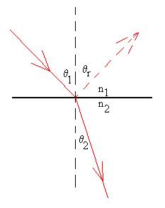
Let's see if we can prove that a change in speed will account for
refraction.
Consider
a wavefront incident on a flat interface at angle q1
(red line), for which we can consider the wave at Point A to be
the
source
for new waves.
A time Dt later,
the
waves created at A are somewhere on the dotted curve a distance
v2Dt
from A, while the upper end of the wavefront still in material
one has
traveled a distance v1Dt
to reach
the interface at Point B. To construct the new wavefront
in
material
two, we know that it must be tangent to the dotted curve (since
it must
be perpendicular to its own direction of motion) and
pass
through
B (blue line).
We observe the two right triangles which
share
a hypoteneuse (H) between Points A & B
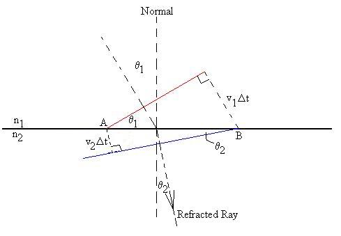
and determine that
H = v1Dt/sinq1
= v2Dt/sinq2,
(c/n1)/sinq1
= (c/n2)/sinq2,
n1sinq1
= n2sinq2.
Newton gave a detailed explanation of how refraction could be accounted for in the corpuscular theory, but we shall not discuss it here, since Foucault showed it to be based on false assumptions. Realize, though, that it was a well respected theory for over 150 years.
Question:
What would happen if n1 = n2?
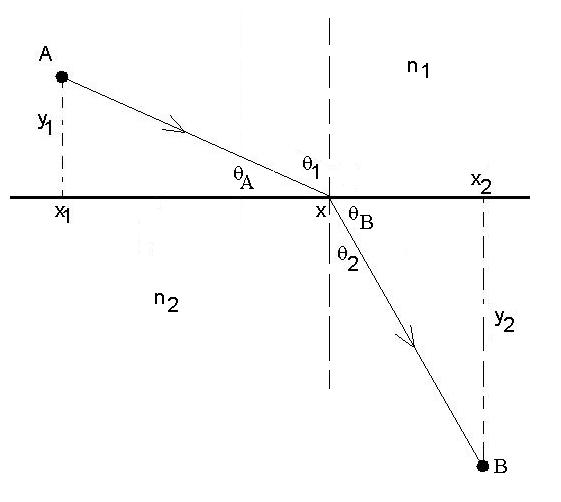
Then set dT/dx = 0
1/2(n1/c)[y12
+ (x1 - x)2]-1/2[2(x1 -
x)(-1)]
+ 1/2(n2/c)[y22 + (x2
- x)2]-1/2[2(x2 - x)(-1)] =
0
- n1[y12
+ (x1 - x)2]-1/2(x1 - x) = n2[y22 + (x2
- x)2]-1/2(x2 - x) = 0
n1
cosqA = n2 cosqB
But,
qA and q1 are
complementary, as are qB and q2 , so
Example:
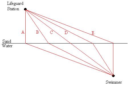
Consider the path a lifeguard should take
across
the beach and through the water to reach a drowning swimmer as
quickly
as possible.
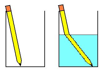
There was a London stage mystery play back
in
the thirties (of which I'm afraid I have forgotton the title) in
which
a major plot device was the fact that the stolen jewels had been
hidden
in a pitcher of water, thus making them invisible. Would
this
really
work?
The index of refraction is also generally wavelength dependent. For example, nglass for light with wavelength 400nm is generally higher than for light of wavelength 700nm. As a result, these two wavelengths will be refracted along slightly different paths. If white light comprising all colours is incident on glass, the colours will be spatially separated, forming a spectrum. Newton coined this expression, because the light so produced appeared 'ghostly.' Natural examples of such spectra include rainbows and sun-dogs.
What about mirrors with a curved surface? We shall restrict ourselves to mirror surfaces which are sections of a sphere, since that will make our derivations a little easier, but you should realize that, in real life, the surfaces could be parabolic or hyperbolic (both common in telescopes) or one of a number of other shapes.
Consider a concave mirror, as shown. We shall draw
in
the
optical axis as a reference line; it passes through the centre of
the
mirror,
perdendicular to its plane. If the surface is part of a
sphere,
there
must be a centre to the sphere (CoS), and the distance of this
point to
the mirror is the radius of curvature of the mirror
surface,
r.
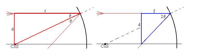
Now, let's consider a ray which comes into the mirror parallel to
the
OA,
a small distance d away from it (the derivation we're about to do
requires
small angles). The ray will hit the mirror surface at an
angle q
and be reflected at the same angle from the normal. How do
we
generate
the normal? It will connect that point on the mirror where the
reflection
takes place to the CoS, i.e., it's a radius of the
sphere.
The ray will return to the left and eventually cross the OA at a
distance
we'll call f from the mirror.
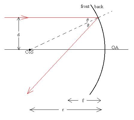
Consider two triangles in this diagram:
Because of the curvature of the mirror, the distances labelled 'r'
and 'f' are not quite r
and f, but for small
values of d, they
will be
close.
For the red triangle, we can write that (at least approximately)
d/r = tanq.
For the blue triangle, we can write that (at least approximately)
d/f = tan(2q),
but since the angles are small, we can re-write this as
d/f = 2 tan(q).
Comparison of the two relations tells us that f = r/2,
and
that
this is true regardless of d. This
last
bit
of information tells us that any ray coming in parallel to
the
OA
will be reflected back through this special point, which we shall
now
call
the
focal point. The distance f is then known as
the
focal
length of the mirror. Note that this result required a
number
of approximations, for example, the angles we used must be small,
and
the
tangents of q and 2q
are actually a little bigger than we said.
In real life, of course, this is not quite true, and spherical
abberation
is the result. Parabolic surfaces do not exhibit such
abberation.
Convex mirrors should also have a focal point, although it is
behind
the surface of the mirror, and the rays don't actually cross
there,
they
only seem to have crossed there:
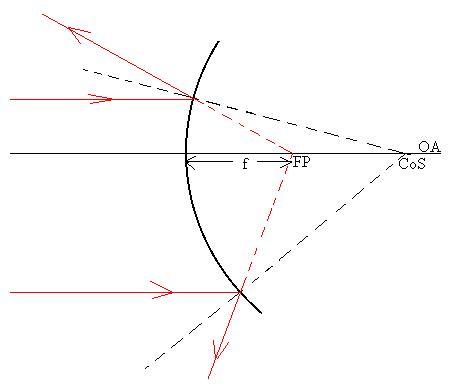
A similar argument can be used to assert once again that f = r/2.
Prove this to yourself.
Let's see if we can use some of this information to predict where
an
image of an object will form. We shall use an arrow as our
object,
because it possesses attributes in which we are interested:
location,
orientation,
size, and as we'll see later, reality or non-reality. The
technique
we're about to use is called ray tracing, and it should be
done
with pencil, paper, and a ruler.
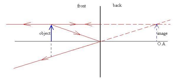
Consider the following situation involving a concave mirror; the
mirror
is drawn flat to aid in the raytracing process, but keep in mind
that
the
surface is actually curved:
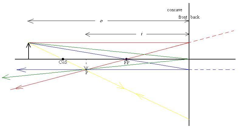
The distance o is called the object distance and
it is
measured from the mirror surface. Consider four rays of
light
which
emanate from the head of the arrow:
Here is another diagram using a concave mirror, with the same
colour
code as above:
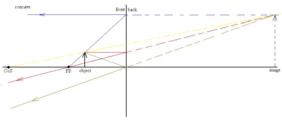
Note that we cannot draw a line from the arrow head through the
focal
point, then to the mirror, so we need to use a trick: draw a ray
(blue)
from the focal point which just grazes the arrow head, continue
onward
toward the mirror, then reflect it back parallel to the OA.
Similarly
for the yellow ray, we start at the centre of the sphere, just
graze
the
tip of the object, and continue from there as before.
How would one describe this image?
Here is an example using a convex mirror:
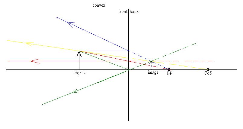
Here, the rays are constructed a little differently, but with a
correspondence
to the four described above:
Describe the image.
Here are the rules we will use for constructing ray diagrams for
converging
lenses:
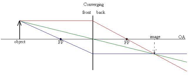
One red ray from the tip of the arrow parallel to the OA, through
the
lens, and bent through the focal point.
One blue ray from the tip of the arrow, through the other focal
point,
hit the lens, and come out parallel to the OA. This is the
the
rule
for the red ray used in reverse.
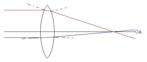
One green ray from the tip of the arrow, through the centre of the
lens undeflected. This last requires some explanation:
Consider a ray which hits near the centre of the lens at some
angle
as shown.
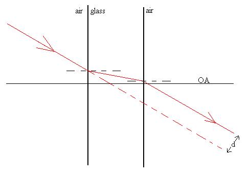
The ray will be refracted at the first surface, which we shall
assume
is essentially perpendicular to the OA. It hits the second
surface,
which is also perpendicular and exits in the same direction as it
was
initially
traveling in. Why?
nair sin qair,left
= nglass sinqglass,
left
= nglass sinqglass,
right
= nair sin qair,right
Note, however, that the ray is offset from its original line of
travel,
but as the thickness of the lens goes toward zero, the amount of
offset
(d) also decreases. So, we conclude that for a thin lens,
the ray
through the centre is undeflected.
Describe the image produced above.
A diverging lens spreads out light coming in parallel to the OA,
so
that it seems to have come from the focal point:
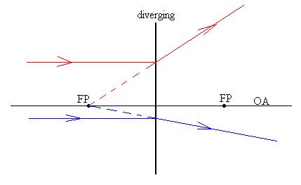
Here is an example of ray tracing for a diverging lens:
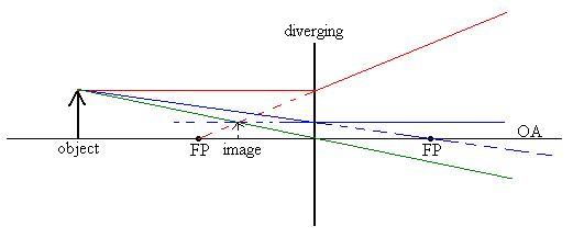
One red ray from the tip of the arrow parallel to the OA, through
the
lens and bent away from the focal point.
One blue ray from the tip of the arrow, towards the other focal
point,
hit the lens, and come out parallel to the OA.
One green ray from the tip of the arrow, through the centre of the
lens undeflected.
Describe this image:
Let's try another converging lens, where the object is inside the
focal
length:
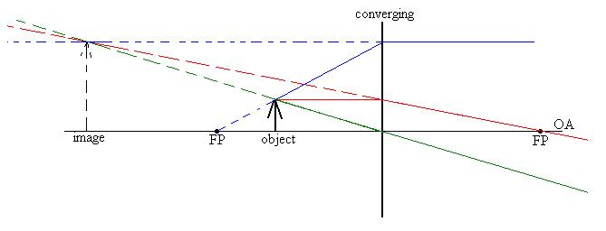
One red ray from the tip of the arrow parallel to the OA, through
the
lens and through the right hand focal point.
Blue ray: here, we had to use our trick again, starting from the
left
hand focal point, just grazing the tip of the arrow, hit the lens,
and
come out parallel to the OA.
One green ray from the tip of the arrow, through the centre of the
lens undeflected.
Describe this image:
Question:
Occasionally, students will ask, 'Which ray (of the many) from the
object will reach the image first?'
If |M| > 1 the image is magnified If |M| < 1 the image is diminished |
Let's briefly consider the meaning of having a 'virtual
object.'
Suppose that there are two (or more) lenses or mirrors through
which
light
must pass. Where will the final image form? What we do
is
consider
each optical element separately. Find the image produced of
the
actual
object by the first optical element, then use that as the object
of the
second element. In some cases the image of the first element
will
form behind the second element, and so we consider it to be a
virtual
object.
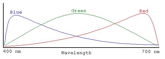
The retina has two basic types of photoreceptors:
Cones, which are concentrated near the center of the
retina
(the
fovea),
appear to be able to distinguish among three basic colors (red,
green,
and blue, each with some overlap into neighboring parts of the
spectrum),
but which are not sensitive to low light levels. The figure is
very
qualitative
and the exact shapes of the curves vary from person to person.
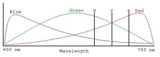
It is thought that light of any single given wavelength
will
excite all three types of photo-receptors in a unique combination;
however,
the correct combination of several wavelengths can produce the
same
sensation
as would a single wavelength not actually present! For
example,
consider
the eye's response to a single wavelength of yellow (589 nm),
which
excites
equal amounts of green and red, plus a little blue, then consider
a
combination
of a red wavelength (670 nm) and a green wavelength (535 nm) which
excites
the eye receptors in the same proportions; that combination will
be
perceived
as yellow, even though no yellow light is actually present.
A second example: Light of just two wavelengths, 480 nm and 580
nm,
can stimulate the same response as a complete spectrum of white
light.
In fact, this is how color televisions work, by using mixtures of
three
basic or primary colors to evoke in the human eye the
sensation
of colors which are not actually present.
Lastly, since the actual response curves can vary from person to
person,
it is entirely possible that one person's orange could look very
different
from another person's orange.
Rods, which are very sensitive to low levels of light, are
more
evenly distributed over the retina, but do not distinguish between
different
colours of light. The photosensitive chemical in the rods is
rhodopsin.
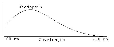
In low light levels, humans lose their color perception (Try it!
Go
out before dawn, and everything is in black and white!), since
only the
rods are receiving enough light to trigger signals to the brain;
at
higher
light levels, the rods shut off and the cones take over.
Normally, in going from a bright room to a dark room, there is a
time
delay until the cones shut off and the rods turn back on.
The
poor
response of rhodopsin in the red part of the spectrum allows
humans to
preserve their night vision by using only red light while
still
indoors. Since the rods' response is not saturated by the
bright
red indoor light, the rods can begin seeing in the dark almost
immediately.
It is thought that photo-chemical reactions in these cells initiate signals sent along nerves to the brain for processing. While most nerve connections for each side of the body are sent to the opposite side of the brain, vision signals from each eye are sent to both sides of the brain.
Question:
Recall the book or films of The Lord of the Flies by
William
Golding. In that story, Piggy's glasses were coveted by both
tribes
of boys as a tool to start fires. What flaw is there in this
plot
device?