Section 2-9 - Wave Optics
Wavelength of Light
in a Material
Young's Double Slit Experiment
Multiple Slits
Single Slit Diffraction
Circular Apertures and
Resolution (Rayleigh's Criterion)
Interference in Thin Films
Polarization
Correlation
to your Textbook.
Wavelength
of Light in a Material
Now,
we
need to go back to thinking about light as a wave, rather than
just as a ray. In the previous section, we showed how
the speed of light is reduced in a material from that in a
vacuum by a factor n, the index of refraction:
v = c/n.
Remember from previous discussions that, for any wave,
v = f l.
So, as light enters a material with a different index, either
f
or l or
both must change as the speed changes. We developed the
idea of frequency as the number of wave crests passing a given
spot per unit of time. If we consider light waves
passing through some interface, it seems clear that the number
of crests incident on the one side must equal the number
exiting on the other, else they would 'pile up' at the
interface like cars in a trafffic
jam. So, the frequency f does not change from
material to material. Clearly, then, we can write that
l'
= lo/n,
that is that the wavelength of light in a material with index
of refraction n is given by the light's wavelength in vacuum (lo)
divided by n.
Young's
Double
Slit Experiment
Thomas
Young
was a pretty remarkable fellow. In Great Experiments
in Physics, Morris Shamos
details his accomplishments:
- Practicing
physician (?!)
- Egyptologist
(both archaeologist & philologist)
- Work
in optics
- Developed
the notion of kinetic energy and defined work as a force
acting through a displacement, Work-Energy Theorem
- Elastic
properties of materials (Young's modulus and the like)
- Theory
of tides
- First
to postulate presence of three color receptors in the human
eye
All
that
and he died at age 56. What's the old joke? When
Mozart was my age, he'd already been dead ten years.
One experiment which really swayed the scientific community toward the wave model was Young's Double Slit Experiment. Young took a barrier with two rectangular openings (or slits) and illuminated them with light of almost a single wavelength. If light were a particle, as Newton suggested, Young would have expected to see two rectangular bright patches when he opened both slits, much the same pattern as if you were to throw spitwads through two openings. What he actually found was that he did not get simply two rectangles, but instead a complicated pattern of varying light and dark. Since he had the advantage of already knowing that these interference effects are present for sound, he deduced that this strange phenomenon could only occur if light was a wave, and in fact, in a speech at the Royal Institution, he dared the Newtonians to explain it using their corpuscular theory.
First, we’ll do an accurate analysis, then we’ll do a derivation that is a bit closer to what’s in your book.
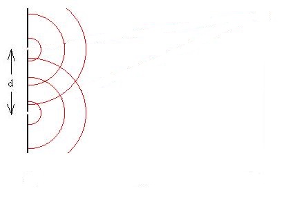
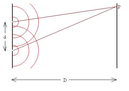
Consider a barrier with monochomatic light of
wavelength l incident
normally. Two slits (seen here in profile) are spaced a
distance d apart. The light passes through the slits
(let's assume that they are infinitely narrow) and travels from
each slit and eventually impinge on a screen a distance D away.
We can now invoke Huygen's Principle to assert that the
slits can be treated as two sources of new waves, which in this
case start out in phase with one another.
Let's follow these two waves along rays to a specific spot in
the space to the right of our barrier.
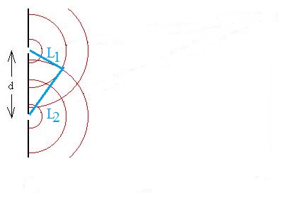
These waves will arrive at our point in phase if the difference between the lengths of the paths taken is a integer number of cycles, or in this case, wavelengths: |L1 - L2| = ml. Such a condition when the two waves add together is called constructive interference.
Can we find the set of points where constructive interference occurs? Well, the condition set forth above is exactly the definition of a hyperbola. So, let's review.
Start with two special points called the focuses, separated by a distance 2c. A hyperbola is the set of points such that the difference in the distances from each such point to each of the two focuses is equal to 2a. The eccentricity of the hyperbola is given by e = c/a, and the equation for the curve is y2/a2 - x2/b2 = 1, where b = (c2 - a2)1/2. In our situation, 2a = ml and 2c = d, the separation between the slits. Substitution and some re-arranging results in
y = ± ml (1/4 + x2/(d2 - m2l2))1/2.
The red lines in the figure represent possible m = 0 and m = 1 curves.
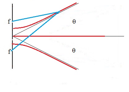
Now, generally, we don't look at the light too close to the barrier, but instead we look at what happens on a screen some distance away. Remember that the arms of a hyperbola approach lines called asymptotes. The angle theta these asymptotes make with the central line is given by
sin q = 1/e.
So, substituting,
sin q = 1/e = 1/(c/a) = 2a/2c = ml/d
or,
d sin q = ml. with m = 0, ±1, ±2, et c. Note, however, that there is a maximum value for m, since the sine function can not exceed one in value.
OK, now let's do this in a more conventional way. Place a screen a distance D from the barrier
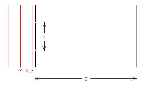
Again, we assert that the slits can be treated as two sources of
new waves which start out in phase with one another. Let's
follow these two waves along rays to a specific spot P on the
screen,
at which point they will have a particular phase relationship
due to the difference (DL)
in the lengths of the path each ray took.
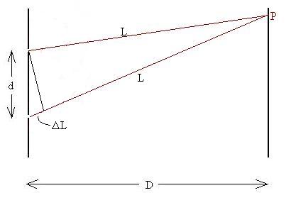
If the difference DL is
an exact integer multiple of the wavelength of the light,
DL = ml,
the waves will arrive in phase, and add together to produce a
bright spot on the screen (constructive interference),
but if the difference is an integer plus one-half times the
wavelength
DL = [m + 1/2]l,
they will arrive out of phase by 180o, and they will
cancel each other resulting in a dark spot on the screen (destructive
interference). Intermediate phase differences will
result in dim, but not dark, spots.
Now, if we assume that D>>d, we can make a couple of
assumptions which will allow us to develop a nice
relationship. Let Point P be a distance x from the line
which perpendicularly bisects the line connecting the
slits. Let the angle q
be that angle from the bisector over to the line directed toward
Point P.
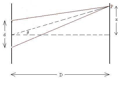
If D>>d, then the line to P and the two path lines are
approximately parallel, that is, they all make the same angle q with the bisector:
The line we drew earlier between the two rays is now
perpendicular to each of them, and by geometry, makes the same
angle theta with the barrier:
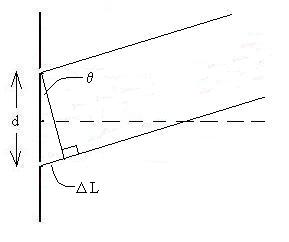
Using a little geometery and
trigonometry, we see that
DL = d sinq.
However, we already know that to produce a bright spot,
DL = ml,
so,
d sinq = ml.
We expect that there will be a number of such angles, so we'll
modify this to
d sinqm = ml; m = 0, +/-1, +/-2,
...
A similar calculation for dark spots gives
d sinqm = [m + 1/2]l; m = 0, +/-1, +/-2, ...
Question: What pattern will be seen if the two sources had been initially 180o out of phase?
As an approximation for small angles, we see that tanq = x/D ~ sinq.
How do we now, in the twenty-first century, reconcile this
'proof' of the wave nature of light with Einstein's 'proof' of
the particle nature of light? We find that, if we shine a
very low level light on a pair of slits and record the pattern
that forms on a photographic plate, that the film does not
register a faint diffraction pattern which gets clearer as time
goes on,
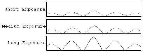
but instead it records a series of random 'hits' of
photons such that the intensity curve we expect to see
represents the statistical frequency with which the photons hit
in different spot.
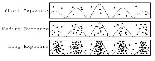
So, even in this single experiment, we can see evidence of both
the wave and particle natures of light!
Now to answer a common question: Why do the maximums get
fainter the farther they are from the central lines? One
reason is that the outlying points are simply farther from the
slits, and we saw in our discussion of sound that the intensity
of a wave falls off with distance from the source. A
second reason is due to the fact that the slits are not
infinitely thin, as we supposed in the derivation.
Factoring this effect in explains why the peak intensities fall
off, and also how they can actually become brighter
again at even greater angles!
However, that effect is too complicated to explain here.
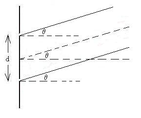
Multiple
Slits
Now,
what
if there had been many (say, N) slits, all very thin and
separated from their nearest neighbours
by d? Certainly, we can see that the very brightest
spots will be formed when all of the waves arrive in phase,
which of course means that rays from adjacent slits are in
phase, and we've already done that calculation:
d sinqm =
ml; m = 0, +/-1, +/-2-, ...
But, we can certainly imagine a situation where only a
majority of waves arrive in phase together, resulting a
smaller maximum. This will involve much trigonometric
calculation, even for low N. But we can once again make
use of the phasor. Draw an arrow with a length
proportional to the amplitude of the light wave from each
source (in red; we'll assume them to be equal) and with a
direction representing the phase. For example (let N =
4), if all waves arrive in phase, we might draw this:
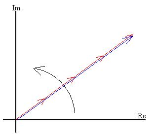
with the blue phasor representing the result.
Now, suppose that we move along the screen so that the waves do
not quite arrive in phase, due to the slightly different path
lengths travelled by each ray:
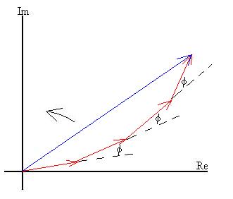
where we see that the amplitude of the sum of the four waves is
reduced. The angle f can
be shown to be
f = 2p DL/l, that is, when f = 2p, DL = l and the arrows all line up
again,
and DL we already
showed for adjacent slits to be
DL = d sin q.
So, f = 2p d sin q/l.
Now, go back to the diagram above. As we increase f, the total amplitude will
decrease, until(for four slits) f = p/2 or 90o:
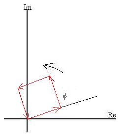
So, the first minimum occurs when
d sin q = 1/4
l.
We can even generalize that result, since the diagram could just
as well represent the case of f
= 360o + 90o, or f = 2x360o + 90o,
to
d sin q = [m + 1/4]
l.
The next maximum occurs when f
= 2p/3 = 120o:
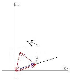
or, when
d sin q = 1/3
l,
and more generally, when
d sin q = [m + 1/3]
l.
Note that this maximum will be much less bright than the last
one; the amplitude is one fourth, and so the intensity is
one-sixteenth.
The next minimum occurs when each successive arrow points 180o
from the previous one (not shown), so that f = p and
d sin q = 1/2
l,
or, more generally, when
d sin q = [m + 1/2]
l.
The next maximum occurs when f
= 4p/3 or 240o;
the phasors would form another equilateral triangle, although
flipped the other way.
d sin q = 2/3
l,
or, more generally,
d sin q = [m + 2/3]
l.
The next minimum will occur when f = 270o or 3p/4, such that
d sin q = 2/3
l,
or, more generally,
d sin q = [m + 2/3]
l.
Then, we're back to where we started with f = 360o, with the waves all in phase again.
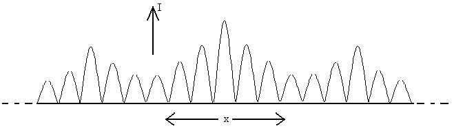
A common situation involving many thousands of slits is the diffraction
grating, used in some spectrometers. In that case,
there are principal maximums which meet the condition
d sinqm = ml; m = 0, +/-1, +/-2-,
...
and many, many secondary maximums which are many times dimmer
than the principal ones, so dim that they can usually be
ignored. The advantage of using a grating instead of a
double slit is that the principal maximums become extremely
narrow, allowing for easy resolution of light from two nearly
identical wavelengths of light.
Single
Slit
Diffraction
What
happens
if light of a single wavelength is incident perpendicularly on
a single slit of width b?
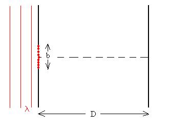
In that case, we have an infinite number of sources (some
shown in red), all in phase with one another. Let's
examine just a couple of very special cases.
Consider what happens at the point on the screen right on the
perpendicular bisector. Look at the point sources in
pairs, starting with the two end points (in red).
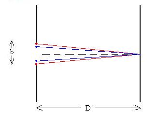
Since the distances from each to the point of observation are
the same, these two waves should arrive in phase with each
other. Now, let's look at the two points just
infinitesimally toward the centre
of the opening (in blue). The distances traveled by the
two rays originating there will also be equal, so that those
waves arrive in phase with each other, and only slightly out of
phase with the first pair we looked at. Now, continue to
look at these rays pairwise; each arrives in phase with its
'pair-mate,' and if D>>b, almost in phase with all
the rest of the rays. So, we should expect a nice bright maximum
at that centre point (at x=0 or
rather q=0).
Let's consider the first minimum or dark spot formed as
the angle theta increases. At this point, all the waves
must cancel out. We might assume that we can once again
use an accounting trick to figure out the conditions necessary,
and we might be right. This time consider the point
sources in pairs, but separated by distance b/2, as shown in the
figure (match the colours):
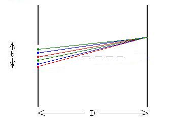
Let's assume again that D>>b, so that the rays are all
approximately parallel. Now consider the two rays marked
off in red:
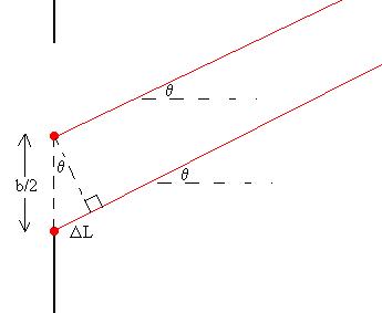
The angles they make with lines parallel to the bisector line
are now both theta, as is the angle marked in the little
triangle. Using some trigonometry, we see that
DL = [b/2] sinq.
We also recall from the discussion above that any difference in
phase in the waves as they arrive at the screen must be due to
the path length difference, DL;
in this case, we are considering the first minimum, so
DL = l/2,
which tells us that
DL = [b/2] sinq = l/2,
or
b sinq = l.
Note the similarity in this relationship to the requirement for
the first maximum in the double slit case. Now,
we've shown that if this requirement is met, these two rays will
cancel. But as we consider all of the other pairs of rays,
each separated from its 'pair-mate' by b/2, we can see that all
of the rays will cancel in pairs, so this will indeed be a
minimum or dark spot on the screen.
Now, that's just the first minimum, how about the others?
Let's repeat the derivation above, but instead of considering
pairs of points separated by b/2, let's do b/4 (we'll have to do
two groups of pairs of points, one group on one side of the centre line and one group on the other
side).
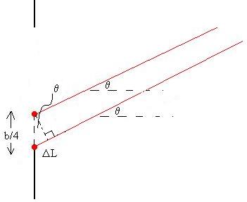
Then,
DL = [b/4] sinq = l/2,
or
b sinq = 2l.
For the nbext minimum, divide the
point sources into three groups of pairs of point sources
separated by b/6. Then
DL = [b/6] sinq = l/2,
or
b sinq = 3l.
We surmise through induction that the minimums occur
when
b sinqm=
m l,
m = +/-1, +/-2, +/-3, ....
Unfortunately, the conditions requried for the maximums or bright spots (other than the central one at q = 0) are not so easy to calculate; they are only approximately mid-way between the minimums, but not exactly.
Circular
Apertures and Resolution
Since
many
optical devices have circular openings rather than rectangular
ones (cameras, eyeballs, et
c.), it seems that we should spend some time dicussing the diffraction from a
circular aperture. We saw previously that a rectangular
aperture will produce a central maximum with an angular half
width of
sin q ~
l/b,
with a number of secondary maximums beyond that angle in both
directions. What we find for the circular aperture of
diameter A is that there will be a central bright disc
with an angular radius of
sin q ~
1.22l/A
with secondary maximums at larger radiuses from the centre.
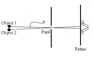
Often, we are concerned whether we can distinguish the images
formed by two objects which lie on nearby sight lines. For
example, two stars, even though we can consider them to be point
sources, will produce images on our retinas which have some
non-zero size, due to the diffraction through our pupils (here,
only the first few maximums are shown for illustration).
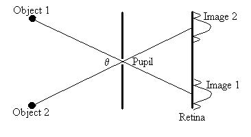
If the images overlap sufficiently, we will not be able to
distinguish them, and we will see one big blob.
Often, we use Rayleigh's Criterion to decide whether the
images overlap too much: if the central maximum of Image One is
closer to the the central maximum
of Image Two than is the first minimum of Image Two, then the
images are not resolvable.
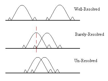
It follows then that, for the images to be resolved,
sin q ~ qradians ~ 1.22l/A,
where A is the aperture (diameter of the opening).
Example: You're out on a flat dark desert and a car is coming toward you. Estimate the minimum distance at which you can resolve the car's two headlights. HINT: Let's guess that the headlights are x = 1m apart (a small car) and that the distance to the car (d) is large compared to that. Then, we could say that the tangent of q is about x/d, which is also about q itself, if expressed in radians. Also, assume that the wavelength of the light is about 550 nm. The eye's aperture on a dark night, maybe 5 mm?
Note that for eyes, there is another consideration to take into account. The cornea has a fairly high index of refraction (~1.5); according to Snell's law, the angle of a ray entering the eye is deflected toward the eye's optical axis by some amount before being diffracted by the pupil, so that the objects to be resolved by the eye must actually be spaced further apart than the equation above suggests. A mitigating factor, though, is that the wavelengths of light passing through the fluids in the eye are shortened by a factor of 1.34 (the index of the fluids), so that the widths of the images are reduced and then so is the minimum angle to meet the Rayleigh criterion.
Example: Consider a 2.2 metre diameter camera in a KH-12 spy satellite in orbit 200 km above the earth. Assuming no atmospheric degradation of vision, what is the smallest separation between two objects on the earth's surface this camera can resolve?
Interference
in Thin Films
Let's
discuss
another example of interference. Consider the effect
seen in water puddles in the parking lot after a rain.
Often, the water will appear to be different colours, almost like a rainbow.
This is caused by interference of light reflected from the
thin film of oil floating on the water. Let's consider
such a film of thickness d and index of refraction n2
atop another material of index n3. Light of
wavelength lo
in vacuum travels from above (let's restrict ourselves to the
special case of normal incidence) vertically through a
material of index n1 and is incident on the upper
interface. In Section 1-14, we saw that mechanical waves
were reflected with phase inversion if Z2>Z1
and without if Z2<Z1. A similar
result is observed with light waves (See note at end of
section): The phase of the electric component of the reflected
wave is inverted on reflection if n2>n1,
and it is not inverted if n2<n1.
So, the ray is partially reflected from the first interface
with a phase change of either 0o or 180o
which we'll represent by PCtop.
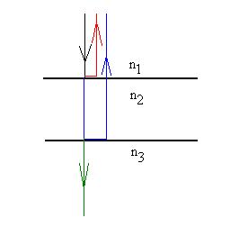
Note that the reflected ray has been drawn schematically with
a slight horizontal offset to aid visualization; in fact, it
passes back up along its original path. The rest of the
ray continues down into Material 2, where it eventually hits
the second interface, at which point some continues down into
Material 3 and some is reflected back upward (with a phase
change PCbottom of
either 0o or 180o) and passes back up
into Material 1. We shall ignore the multiple
reflections which acually
occur. It is these two rays we will concern ourselves
with: the first reflection from the top interface (red) and
the light from the first reflection at the second interface
(blue). If these two rays are in phase, we will see a
bright reflection, and if they are completely out of phase,
there will be no reflection. Also, note that there is
also some light transmitted through into Material 3.
FIGURE
We can tentatively write that
|
PCtop + PCbottom
= |
an integer number of cycles (constructive
interference or bright reflection) |
|
|
an integer number of cycles plus one half
cycle (destructive interference or no reflection). |
Now, this result isn't quite right, because there is another consideration which contributes to the phase difference between the rays. Remember that in our discussions of the single and double slit situations there was a phase difference introduced when one wave traveled a longer distance than the other did. How much farther does the ray reflected from the lower interface travel than does the one reflected from the top?
So, we should change this to:
|
PCtop + PCbottom
+ 2d = |
an integer number of cycles (constructive
interference or bright reflection) |
|
|
an integer number of cycles plus one half
cycle (destructive interference or no reflection). |
We see, though, that there is now a dimensional mismatch, in
that the PC terms and the right hand side (measured in degrees
or cycles) are dimensionless and the distance term (2d) has
dimension [Length]. We'll fix that by using the wavelength
of the light in material two (l2)
as the distance equivalent of a cycle, inserting 0 for 0o
and l2/2 for
180o. We need to use l2 because we
need to know how many extra wavelengths (cycles) are included in
the distance 2d inside material two.
|
PCtop(0 or l2/2) + PCbottom(0
or l2/2) + 2d = |
ml2 (constructive interference or bright
reflection) |
|
|
[m + 1/2]l2 (destructive interference or no
reflection). |
It's probably more convenient to write this relationship in
terms of the wavelength in vacuum: l2 = lo/n2.
Making this substitution and multiplying through by n2
gives our final result:
|
PCtop(0 or lo/2) + PCbottom(0
or l0/2) + 2n2d = |
mlo (constructive interference or bright
reflection) |
|
|
[m + 1/2]lo (destructive interference or no
reflection). |
Question:
Why do the lenses of the more expensive cameras appear to be
purple (actually magenta)?
Example:
Suppose that a thin film of oil (index = 1.2) floats on top of
water. Light of wavelength lo = 600 nm is
incident normally on the surface and produces a very bright
reflection. How thick is the oil film?
We have a bright reflection, so let's assume constructive
interference:
PCtop + PCbottom + 2n2d
= mlo
Since n2>n1
and n3>n2, there are 180o
phase changes (write lo/2)
at each interface:
lo/2
+ lo/2
+ 2n2d = mlo.
Here's a neat trick: the two half lambdas add to one whole
lambda, which represents a complete cycle. But
phase-wise, a difference of a complete cycle is the same as a
difference of zero. So, in spite of being added, those
two terms can actually cancel. We now have:
2n2d = mlo.
Then,
d = mlo/2n2
= m*600/(2*1.2) = m*250 nm.
The case m=0 corresponds to there being only one interface and
no oil layer; there will be a fairly bright reflection but no
interference. The case m=1 is the thinnest such
oil film which meets our requirements, but other thicknesses
(m>1) will also work.
Example:
What wavelengths of light will produce bright reflections from a
soap-water film of thickness 500nm and index of refraction 1.4?
Assume that the film has air on each side, so that n2>n1
but n2>n3. Then,
lo/2
+ 0 + 2n2d = mlo.
2n2d = [m - 1/2]lo.
lo=
2n2d/[m
- 1/2].
The case m = 0 doesn't make sense, so go to m=1, and so on.
Please note that this way of looking at the situation is very
different then the way presented in your text, which probably
asks you to memorize different formulas for different
situations. This method, although slightly cumbersome,
works in all cases.
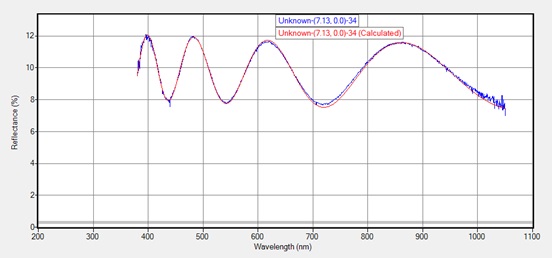
Reflection Spectrum of a sapphire film on Gorilla Glass.
Polarization
Now,
let's
return to the original picture of light as an electro-magnetic
wave which was introduced at the start of Section 8. We
had mentioned that the electric field could oscillate in
different directions for any given direction of propagation.
FIGURE
Polarization of light can be accomplished in a number of ways.
- EM
waves can be generated by accelerating electrical
particles. High energy electrons orbiting in a
magnetic field give rise to synchotron
radiation, which is polarized. Low energy
electrons give rise to cyclotron radiation, which is
also polarized.
- Reflecting
light off of a surface at just the right angle (the Brewster's
angle: tanqB =
n2/n1). We'll get back to this
later.
- Passing
the light through a polarizer, as invented by Land
in the '30s.
Let's
discuss
this last. A commercial polarizer consists of a plastic
with many long, thin polymer chains aligned parallel
to one another. Treating the chains with certain
chemicals renders them electrically conducting.
Electrons in each molecule can them move very easily along the
chains, but not easily perdendicularly
to the length of the chain. When light is incident on
the molecules, the components of the electric fields parallel
to the chains make the electrons move up and down the chains
and are thus absorbed, while the electric field components
oriented perdendicularly to the
chains are not absorbed and so pass through. An analogy
to this might be a string passes between the slats in the back
of a kitchen chair; a wave with displacement in the vertical
plane will pass through the chairback
unhindered, but one with displacement in the horizontal plane
will be stopped.
An ideal polarizer, one made of a material with no
intrinsic absorption, will pass 50% of an initially unpolarized beam (see note) of light:
I = 1/2 Io (unpolarized light).
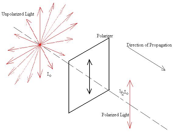
Suppose that the red arrows represent the electric field vectors
of some number of equal intensity waves which are heading out of
the page:
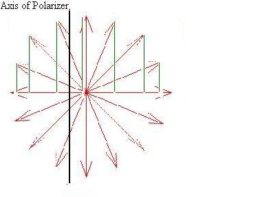
The components that survive the polarizer (that is which are
parallel to the axis of the polarizer) are represented by the
green lines (the components on the other side can be thought of
as just the other halves of the waves already counted). If
we add them all up and square the result (remember that I ~ E2),
we get a factor of 1/2. Also, the
light exiting the polarizer will be polarized in the direction
parallel to the polarization axis of the polarizer.
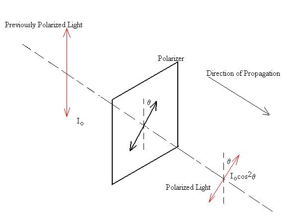
If previously polarized light is incident on an ideal
polarizer, the transmitted intensity is given by:
I = Io cos2q,
where q is the angle
between the initial plane of polarization and the axis of the
polarizer. The transmitted light will be polarized in the
same plane as the polarization axis of the polarizer.
The origin of the cosine squared term should be clear to
you. Once again, consider the components of the electric
field:
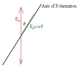
Only the component of the original electric field in the
direction of the polarizer's axis will be transmitted; that is
to say, Eocosq. Since the intensity
goes as E2, we obtain the cosine squared term.
Question:
In class, we saw that crossed polarizers allow no light to be
transmitted. The first polarizer polarizes the transmitted
light along a plane we'll refer to as the 0o
plane. The second polarizer has its axis at right angles
to this, so the angle theta is 90o; since
cos90o = 0, there is no light transmitted.
However, we that that when a third polarizer is inserted between
the original two, some light does get transmitted.
How is this so? How much light gets through?
Click here for the explanation.
A
Note for Those Who Care
The
optical
impedance of a non-conducting material is given by Z = [mo/keo]1/2 =
Zvacuum/n. Note
the similarities between electromagnetic waves and transverse
waves on a string:
|
Velocity |
Impedance |
|
|
Wave on a String |
v = [T/m]1/2 |
Z = [Tm]1/2 |
|
EM Wave |
v = [1/keomo]1/2 |
Z = [mo/keo]1/2 |
The
same
rules regarding the inversion of the reflected waves when
encountering an interface are the same as for strings if
we consider the magnetic field of the wave; the electric field
component follows the reverse, namely inversion on
reflection when going from high Z to low Z (low n to high n),
and no inversion from low Z to high Z (high n to low n).
A
Note for the Truly AR
Unpolarized
light really means that the light observed contains equal
numbers of waves (which are individually polarized) from many
sources, but which when added together exhibit no preferred
plane of oscillation.
D Baum - 2002