Again using the standard co-ordinate system of +y up and +x to the right, and picking the left end of the beam as the pivot, we write that:
Our convention for this chapter is that we shall write the
magnitudes
of the forces and r vectors, then add the appropriate signs in front of
each torque term; positive for torques out of the page (that is, those
which would act to accelerate the object CCW), and negative for torques
into the page (those which would act to accelerate the object CW).
So,
Si (Fi )x
= 0 (There are no horizontal forces)
Si (Fi )y
= N - mAg - mg - mCg = 0
Next, we choose a pivot point. Unlike in previous
problems,
the object is not actually rotating, so the sum of the torques as
calculated
about any point has to be zero; so, let's pick a point which is
convenient for us. Let's pick two such points and do the problem
twice to illustrate a point:
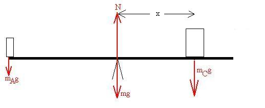
| We might notice that, if we were to
pick the
fulcum as the pivot, that the weight of the board and the normal force would exert no torque, thus simplifying the calculation: Si ti = +(mAg)(L/2)(sin90o) + (N)(0) + (mg)(0) - (mCg)(x)(sin90o) = 0 where x is the distance of Carli from the fulcrum. With this pivot, we do not even need the force equations, since (mAg)(L/2)(sin90o) = (mCg)(x)(sin90o) mAL/2 = mCx x = (mAL)/(2mC) = 2.3 m Note that we didn't really need to know the weight of the board either. |
We might choose the left end of the
board as
the pivot; then the torque requirement is: Si ti = +(mAg)(0)) + (N)(L/2)(sin90o) - (mg)(L/2)(sin90o) - (mCg)(L/2 + x)(sin90o) = 0 where x is the distance of Carli from the fulcrum. 2N - 2mg - mCg(1 + 2x/L) = 0 Then, from the force equation: N = mAg + mg + mCg Substitute: (mAg + mg + mCg ) - mg - mCg(1 + 2x/L) = 0 mA - mC 2x/L = 0 mA = mC 2x/L x = (mAL)/(mC2) = 2.3 m |
So, even though this was a simple example, we see that a judicious
choice
of the pivot can save a great deal of work.
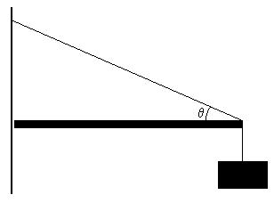
Consider a horizontal uniform beam of mass m and length L supporting
a sign of mass M. The beam is attatched to the wall with a wire
which
makes an angle q with the beam. Its
other
end is supported by the friction between the end of the beam and the
wall.
How large would the co-efficient of static friction need to be to keep
the beam from slipping?
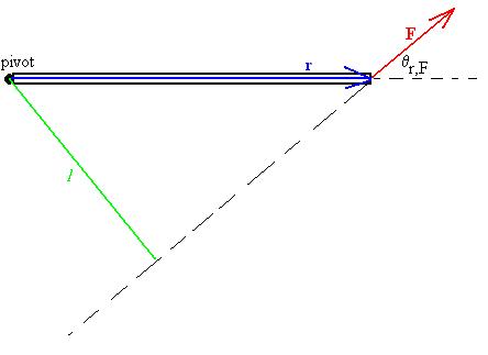
Again using the standard co-ordinate system of +y up and +x to the
right, and picking the left end of the beam as the pivot, we write
that:
Si (Fi )x
= N - T cosq = 0
Si (Fi )y
= Ff - mg - Mg + Tsinq =
0
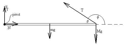
(again, the Mg term is not literally the weight of the sign, but
a tension term numerically equal to the weight)
Si ti
=
Ff(0) + N(0) - mgL/2 - MgL + TL sinf
= 0 which becomes Tsinq
= mg/2 + Mg
Now, the angle theta shown in the figure is not really the angle we're
supposed to take the sine of, but rather its supplement, but that's
O.K.,
since their sines will be the same.
In addition, Ff = mSN
(critical case of teh minimum value for mS
to prevent slipping).
So, now it's just math:
mS= Ff /N = [mg +
Mg - Tsinq]/[T cosq]
Substitution for T gives us
mS= [mg/2]/[(mg/2
+ Mg)/tanq] = m tanq/[m
+ 2M].